KIA Niro: Dual Clutch Assembly
Components
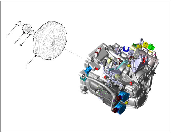
- Retaining ring
- Spline hub
- Snap ring
- Dual clutch assembly
Dual Clutch Assembly Repair procedures
Removal
- Remove the hybrid drive motor & dual clutch transmission assembly from
the vehicle.
(Refer to DCT System - "DCT")
- Remove the hybrid drive motor assembly from the DCT assembly.
(Refer to Hybrid Motor System - "Hybrid Drive Motor Assembly")
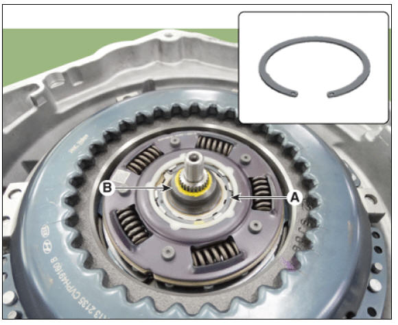
- Remove the spline hub (B) after removing a retaining ring (A).

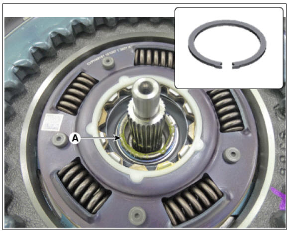
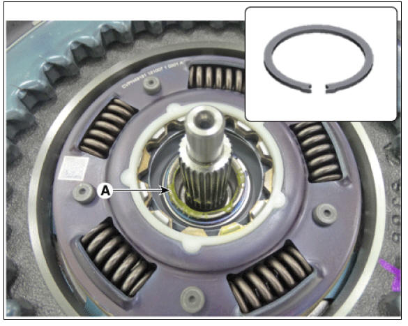
- Remove the snap ring (A).
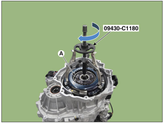
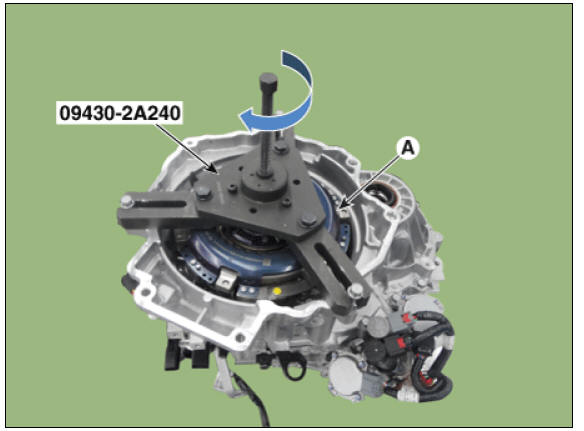
- Remove the dual clutch assembly (A) by using the special service tool (09430-C1180).
Installation
Warning
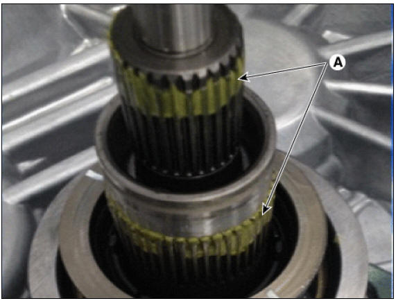
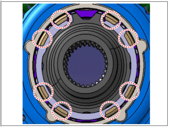
- Check that the input shaft spline part (A) is sufficiently greased before installing the dual clutch assembly. If the input shaft spline part is not greased, apply the grease to 10 mm (0.3937 in.) on each spline end.
- If an excessive amount of grease is applied, it may get scattered by centrifugal force, contaminating the clutch disc. This can lead to loss of friction force.
Specified grease : Extreme pressure grease for vehicle
Quantity : 0.15 - 0.25 g
- If dual clutch assembly needs replacement, perform the clutch wear
compensation Initialize.
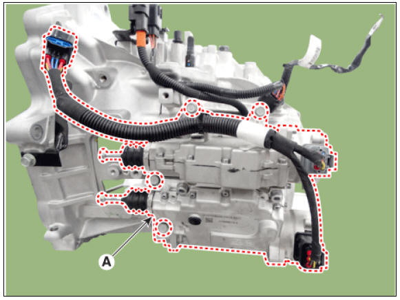
(1) Remove the fork cover (A).

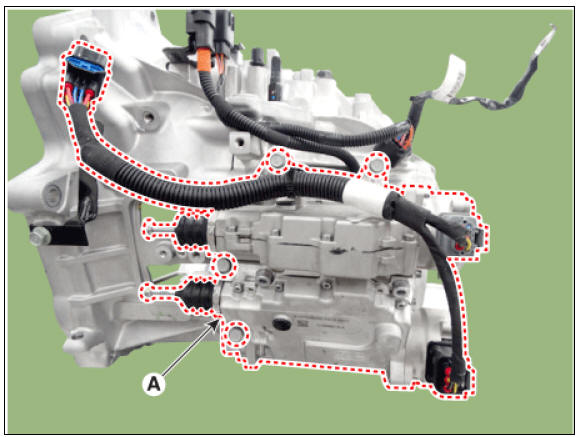
(2) Remove the clutch actuator assembly (A).
(3) Perform the clutch wear compensation Initialize.
(Refer to Double Clutch Transmission Control System - "Clutch Actuator Assembly")
(4) Install the the clutch actuator assembly (A).
Tightening torque : 19.6 - 26.5 N*m (2.0 - 2.7 kgf*m, 14.5 - 19.5 lb*ft)
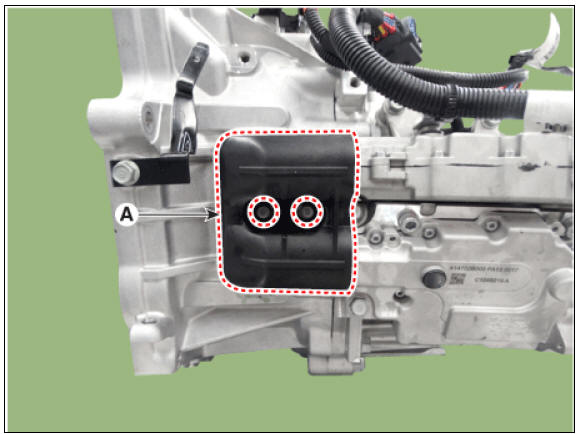
(5) Install the fork cover (A).
Tightening torque : 3.9 - 5.9 N*m (0.4 - 0.6 kgf*m, 2.9 - 4.3 lb*ft)
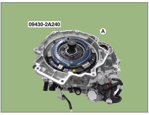
- Install the double clutch assembly (A) by using double clutch installer (09430-2A240).
- Install the snap ring (A).
- Install the spline hub (B) and the retaining ring (A).
Warning
Check the installation condition of retaining ring after installing.
- Install the hybrid drive motor assembly to the DCT assembly.
(Refer to Hybrid Motor System - "Hybrid Drive Motor Assembly")
- Install the hybrid drive motor & dual clutch transmission assembly to
the vehicle.
(Refer to DCT System - "DCT")
READ NEXT:
 Clutch Engagement Fork and Engagement Bearin
Components
Engagement bearing 2 (Even)
Engagement bearing 1 (Odd)
Engagement bearing sleeve
Engagement fork 1 (Odd)
Engagement fork 2 (Even)
Clutch Engagement Fork and Engagement Bearing Repair procedures
Removal
Remove the du
Hybrid Motor System
Specifications
Hybrid Drive Motor
Hybrid Starter Generator (HSG)
Electric Water Pump (EWP)
Coolant
Tightening Torques
Special Service Tools
Tool Name /
Number/
Illustration / Description
Pressure cap
pressure
checke
SEE MORE:
Replacing glove box lamp (Bulb type)
Operation
Using a flat-blade screwdriver, gently
pry the lamp assembly from interior.
Remove the cover from the lamp
assembly.
Remove the bulb by pulling it straight
out.
Install a new bulb in the socket.
Install the cover
Next departure
A: Electric vehicle
Next departure
Select EV → Next departure on the
screen. You can set the date and time of
when to charge the battery, climate control
temperature, and other various
functions.
Departure time
A: Next departur
Categories
- Home
- KIA Niro EV, Hybrid - Second generation - (SG2) (2021-2024) - Owner's manual
- Kia Niro - First generation - (DE) (2017-2022) - Service and Repair Manual
- Contact Us