KIA Niro: Injector
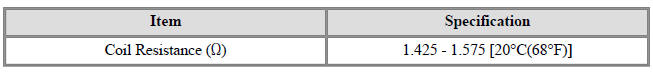
Specification
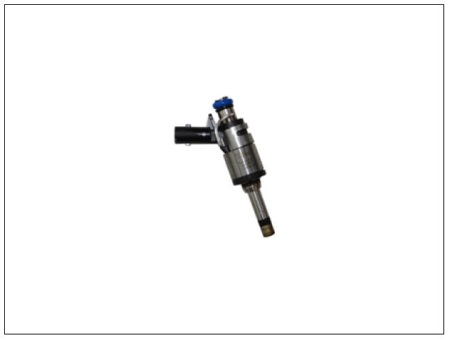
Description
The GDI injector is similar to a standard injector, but sprays fuel at a much
higher pressure directly
into the combustion chamber and has a swirl disc to get the fuel swirling as it
exits the nozzle. This
aids in atomization of the fuel.
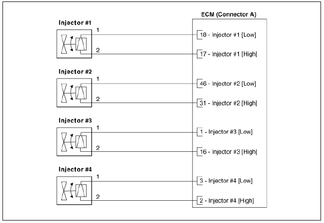
The ECM controls both the feed circuits (high side) to feed voltage to the injectors and the ground circuits (low side) to energize the injectors. Also, the feed for 2 injectors comes from the same driver set. As the ignition coils are paired with cylinders (1-4 and 2-3), the injectors are also set up in pairs.
Circuit Diagram
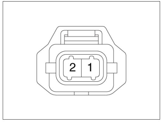
Harness Connector
Inspection
- Switch "OFF" the ignition.
- Disconnect the injector connector.
- Measure resistance between the injector terminals 1 and 2.
- Check that the resistance is within the specification.
Specification: 1.425 - 1.575 Ω (20ºC(68ºF))
Injector Repair procedures
Removal
Warning
In case of removing the high pressure fuel pump, high pressure fuel pipe, delivery pipe, and injector, there may be injury caused by leakage of the high pressure fuel. So don't do any repair work right after engine stops.
- Release the residual pressure in fuel line.
(Refer to the Fuel Delivery System - "Release Residual Pressure in Fuel Line")
- Switch "OFF" the ignition and disconnect the negative (-) battery terminal.
- Remove the intake manifold.
(Refer to Engine Mechanical System - "Intake Manifold")
- Remove the delivery pipe & injector assembly.
(Refer to Fuel Delivery System - "Delivery Pipe")
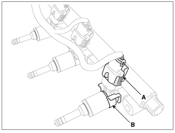
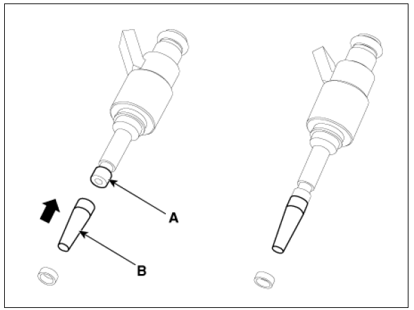
- Remove the connector (A) and the fixing clip (B), and then separate the injector from the delivery pipe.
Installation
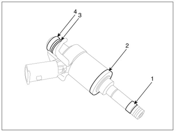
- Combustion seal
- Rubber washer
- Support disc
- O-ring
Warning
- Do not reuse the used injector fixing clip.
- Install the component to the specified torque.
- Note that internal damage may occur when the component is dropped. If the component has been dropped, inspect before installing.
- Apply engine oil to the injector O-ring.
- Do not reuse the used injector O-ring.
- Do not reuse bolts.
- When inserting the injector, be careful not to damage the injector tip.
- Do not reuse the high pressure fuel pipe.
- Do not reuse the support disc.
- Do not reuse the injector rubber washer.
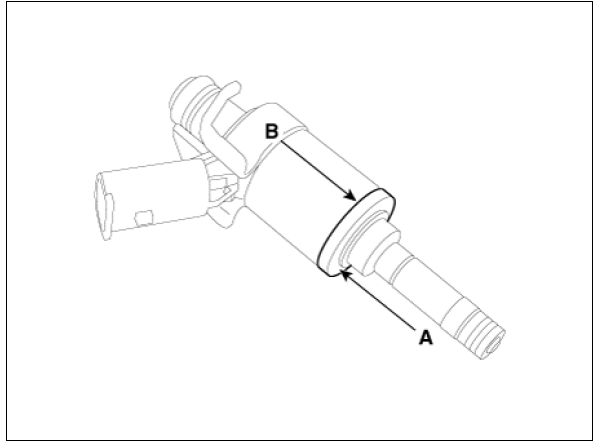
- When replacing the rubber washer, the steal plate (A) part should be facing the cylinder installation part and the rubber plate (B) part should be facing the injector body part.
Warning
Do not reuse the combustion seal.
- Install in the reverse order of removal.
Replacement
The injector combustion seal should be replaced with a new one to prevent leakage after removing the injector.
- Remove the combustion seal (A) with a wire cutter.
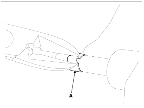
Warning
Carefully pinch the sealing ring into a small loop, and then cut it.
Be careful not to damage the surface of the valve sleeve with the wire cutter.
- Before assembling the sealing ring, clean the groove with a clean cloth.
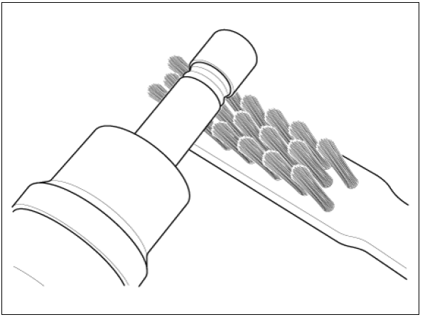
Any coking of the injector sealing surface must be carefully removed with a brass-wire brush.
Warning
The surfaces of the new sealing ring must be clean and free of grease.
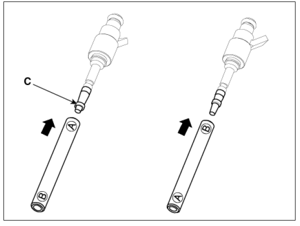
- Place the seal installation guide (B) (SST No.: 09353-2B000) on the tip
of the injector without damaging the
injector tip (A).
Push the sealing ring (C) with thumb and index finger over the conical assembly tool until it snaps into the groove.
The complete assembly must not take longer than 2 to 3 seconds.
- To size the sealing ring the injector is first introduced into the sizing tool (A) (SST No.: 09353-2B000) and then pressed and at the same time rotated 180º into the sizing tool.
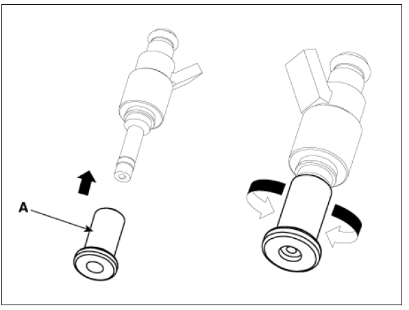
- Pull the injector out of the sizing tool by turning it in the reverse direction of the press-in process.
Warning
Check that the seal ring has not been damaged during assembly to the
injector and that no
circumferential scratches are present.
Do not reuse the combustion seal.
The seal must be completely free of grease and oil.
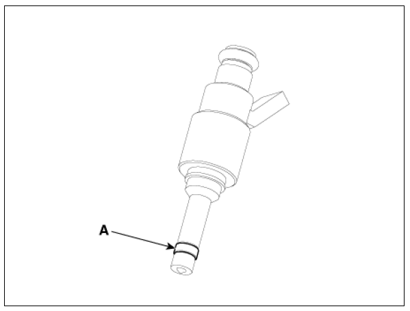
- Check the combustion seal (A) installation.
Signal
Waveform
The three waveforms below are taken from the #1 and #4 injectors. The top waveform is from the high side (feed side) of the #1 and #4 injectors, while the middle waveform is from the low side (ground side) of the #1 injector and the bottom waveform is from the low side of the #4 injector.
The middle waveform is the same as the top waveform because there is no ground for the circuit. With no current flowing in the circuit, the #1 injector is not energized and fuel does not flow.
The bottom waveform shows that ground is supplied and there is a voltage drop across the #4 injector. With current flowing in the circuit, the #4 injector is energized and fuel flows.
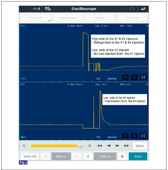 Fig.2) Normal Waveforms of Injector at Engine idle
READ NEXT:
 Purge Control Solenoid Valve (PCSV)
Specification
Purge Control Solenoid Valve (PCSV) Description and operation
Description
Installed on the intake manifold, the Purge Control Solenoid Valve (PCSV)
controls the evaporative
purge between the canister and the intake manifold. I
Variable Force Solenoid (VFS)
Description
Continuous Variable Valve Timing (CVVT) system advances or retards the valve
timing of the intake
and exhaust valve in accordance with the ECM control signal which is calculated
by the engine speed
and load.By controlling CVVT, the
CVVT Oil Control Valve (OCV)
Specification
Bank 1 / Exhaust
Description
Continuous Variable Valve Timing (CVVT) system advances or retards the valve
timing of the intake
and exhaust valve in accordance with the ECM control signal which is calculated
by the engine spe
SEE MORE:
Forward Collision-Avoidance Assist settings
Forward safety
A: Driver Assistance
Driving Safety
Forward Safety
With the vehicle on, touch Settings →
Driver Assistance → Driving Safety on
the instrument cluster or Settings →
Vehicle → Driver Assistance → Driving
S
Climate control system components
A: Outside air
B: Recirculated air
C: Climate control air filter
D: Blower
E: Evaporator core
F: Heater core
The climate control air filter installed
behind the glove box filters the dust or
other pollutants that come into the v
Categories
- Home
- KIA Niro EV, Hybrid - Second generation - (SG2) (2021-2024) - Owner's manual
- Kia Niro - First generation - (DE) (2017-2022) - Service and Repair Manual
- Contact Us