KIA Niro: Engine Control System
Kia Niro - First generation - (DE) (2017-2022) - Service and Repair Manual / Engine Control / Fuel System / Engine Control System
Components
Location
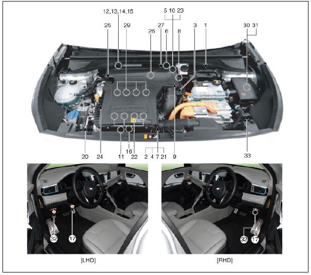
- Engine Control Module (ECM)
- Manifold Absolute Pressure Sensor (MAPS)
- Mass Air Flow Sensor (MAFS)
- Intake Air Temperature Sensor (IATS)
- Engine Coolant Temperature Sensor (ECTS) (Water Temperature Control Assembly)
- Engine Coolant Temperature Sensor (ECTS) (EGR Cooler Tube)
- Throttle Position Sensor (TPS) (integrated into ETC Module)
- Crankshaft Position Sensor (CKPS)
- Camshaft Position Sensor (CMPS) (Bank 1 / Intake)
- Camshaft Position Sensor (CMPS) (Bank 1 / Exhaust)
- Knock Sensor (KS)
- Heated Oxygen Sensor (HO2S) (Bank 1 / Sensor 1)
- Heated Oxygen Sensor (HO2S) (Bank 1 / Sensor 2)
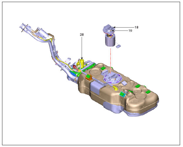
- Exhaust Gas Temperature Sensor (EGTS) #1 (T3)
- Exhaust Gas Temperature Sensor (EGTS) #2 (T4)
- Rail Pressure Sensor (RPS)
- Accelerator Position Sensor (APS)
- Fuel Tank Pressure Sensor (FTPS)
- Fuel Pressure Sensor (FPS)
- A/C Pressure Transducer (APT)
- ETC Motor (integrated into ETC Module)
- Injector
- Purge Control Solenoid Valve (PCSV)
- Variable force solenoid (Bank 1 / Intake)
- CVVT Oil Control Valve (OCV) (Bank 1 / Exhaust)
- Fuel Pressure Control Valve (FPCV)
- Electric EGR Control Valve
- Fuel Tank Isolation Valve (FTIV)
- Ignition Coil
- Main Relay
- Fuel Pump Relay
- Data Link Connector (DLC) (16-Pin)
- Multi-Purpose Check Connector (20-Pin)
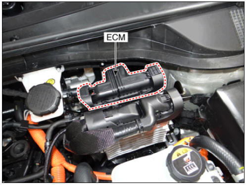
- ECM (Engine Control Module)
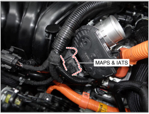
- Manifold Absolute Pressure Sensor (MAPS)
- Intake Air Temperature Sensor (IATS)
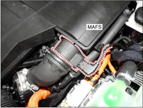
- Mass Air Flow Sensor (MAFS)
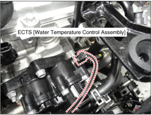
- Engine Coolant Temperature Sensor (ECTS) (Water Temperature Control Assembly)
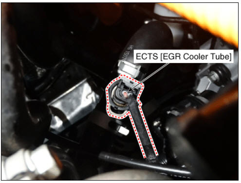
- Engine Coolant Temperature Sensor (ECTS) (EGR Cooler Tube)
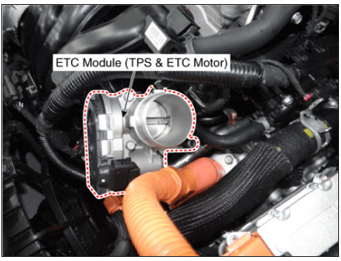
- Throttle Position Sensor (TPS) (integrated into ETC Module)
- ETC Motor (integrated into ETC Module)
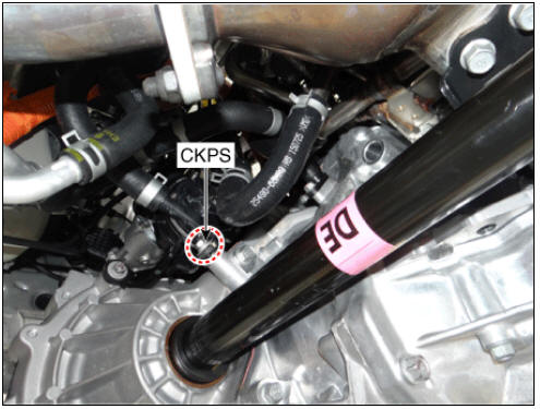
- Crankshaft Position Sensor (CKPS)
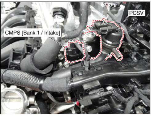
- Camshaft Position Sensor (CMPS) (Bank 1 / Intake)
- Purge control solenoid valve (PCSV)
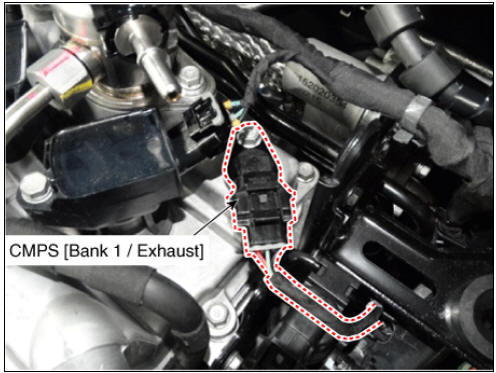
- Camshaft Position Sensor (CMPS) (Bank 1 / Exhaust)
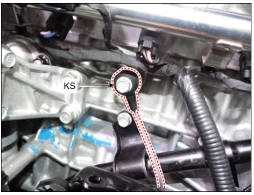
- Knock Sensor (KS)
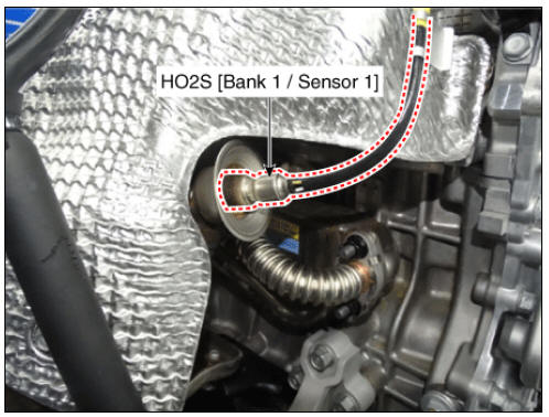
- Heated Oxygen Sensor (HO2S) (Bank 1 / Sensor 1)
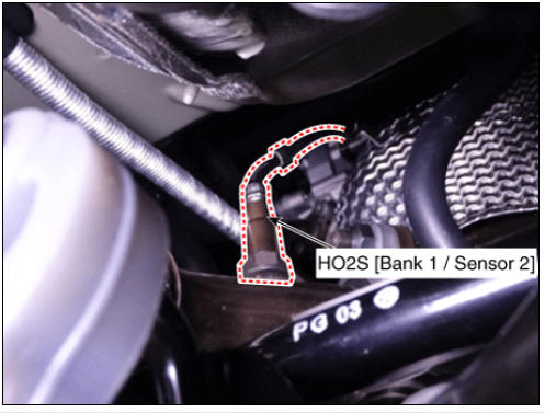
- Heated Oxygen Sensor (HO2S) (Bank 1 / Sensor 2)
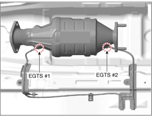
- Exhaust Gas Temperature Sensor (EGTS) #1 (T3)
- Exhaust Gas Temperature Sensor (EGTS) #2 (T4)
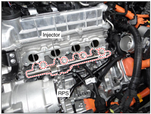
- Rail Pressure Sensor (RPS)
- Injector
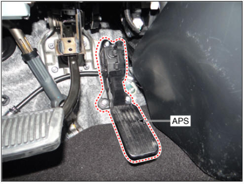
- Accelerator Position Sensor (APS)
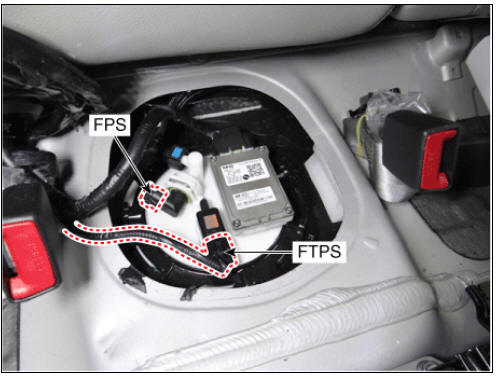
- Fuel Tank Pressure Sensor (FTPS)
- Fuel Pressure Sensor (FPS)
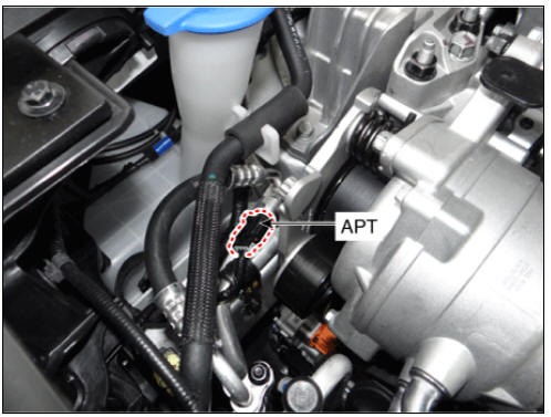
- A/C Pressure Transduc,APT)
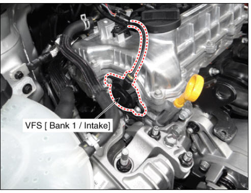
- Variable Force Solenoid (VFS) ( Bank 1 / Intake)
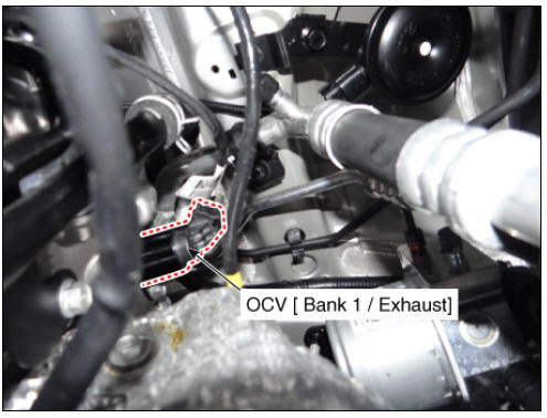
- CVVT Oil Control Valve (OCV) ( Bank 1 / Exhaust)
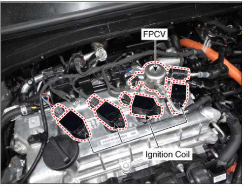
- Fuel Pressure Control Valve (FPCV)
- Ignition Coil
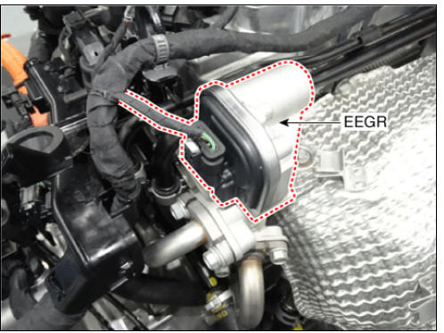
- Electric EGR Control Valve
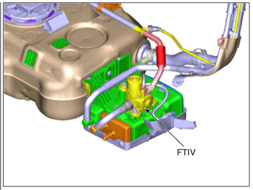
- Fuel Tank Isolation Valve (FTIV)
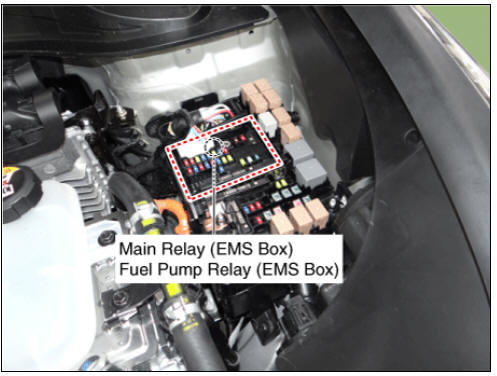
- Main Relay (EMS Box)
- Fuel Pump Relay (EMS Box)
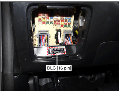
- Data Link Connector (DLC) (16 pin)
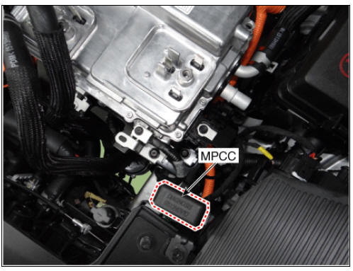
- Multi-Purpose Check Connector (20 pin)
- Engine Control System / Description And Operation
- Engine Control Module (ECM) Repair procedures
- ETC (Electronic Throttle Control) System Repair
- Manifold Absolute Pressure Sensor (MAPS)
- Mass Air Flow Sensor (MAFS)
- Intake Air Temperature Sensor (IATS)
- Engine Coolant Temperature Sensor (ECTS)
- Crankshaft Position Sensor (CKPS)
- Camshaft Position Sensor (CMPS)
- Knock Sensor (KS)
- Heated Oxygen Sensor (HO2S)
- Rail Pressure Sensor (RPS)
- Accelerator Position Sensor (APS)
- Injector
- Purge Control Solenoid Valve (PCSV)
- Variable Force Solenoid (VFS)
- CVVT Oil Control Valve (OCV)
- Fuel Pressure Control Valve (FPCV)
- Electric EGR Control Valve
READ NEXT:
 Engine Control System / Description And Operation
Description
If the Gasoline Engine Control system components (sensors, ECM, injector, etc.)
fail, interruption to the fuel supply or failure
to supply the proper amount of fuel for various engine operating conditions will
result. The following
Engine Control Module (ECM) Repair procedures
ECM Terminal And Input/Output signal
ECM Terminal Function
Connector (A)
Connector (K)
ECM Terminal Input/Output Signal
Connector (A)
Connector (K)
Engine Control Module (ECM)
ETC (Electronic Throttle Control) System Repair
Inspection
Connect the KDS on the Data Link Connector (DLC).
Start the engine and measure the output voltage of TPS 1 and 2 at C.T.
and W.O.T.
Throttle Position Sensor (TPS)
ETC Motor
Switch "OFF" the ignition.
Discon
SEE MORE:
Main/ Sub High Voltage Battery
Main High Voltage Battery
Power Relay Assembly (PRA)
Cell Monitoring Unit (CMU)
Battery Temperature Sensor
Runaway Arresting Device (RAD)
Warning
Main Relays (Positive, Negative), Pre-Charge Relay, Pre-Charge
Resistor, and Battery
LCD display messages (Kia NIRO Hybrid)
For Plug-in hybrid vehicle (Kia NIRO Hybrid)
LCD displays/ Displayed contents
Door, hood, tailgate, sunroof
open
Low tire pressure warning
display
A: Low tire pressure
A: Lights
1:
2:
3: AUTO
4: OFF (O)
A
Categories
- Home
- KIA Niro EV, Hybrid - Second generation - (SG2) (2021-2024) - Owner's manual
- Kia Niro - First generation - (DE) (2017-2022) - Service and Repair Manual
- Contact Us