KIA Niro: Instrument Cluster Repair procedures
Kia Niro - First generation - (DE) (2017-2022) - Service and Repair Manual / Body Electrical System / Indicators And Gauges / Instrument Cluster Repair procedures
Removal
Warning
- Put on gloves to protect your hands.
- When removing with a flat-tip screwdriver or remover, wrap protective tape around the tools to prevent damage to components.
Instrument Cluster
- Disconnect the negative (-) battery terminal.
- Remove the cluster fascia panel.
(Refer to Body - "Cluster Fascia Panel")
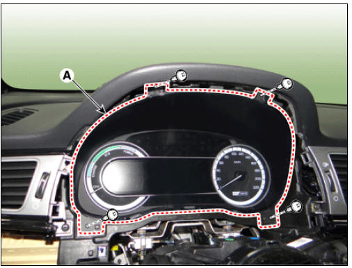
- Remove the instrument cluster (A) after loosening the mounting screws.
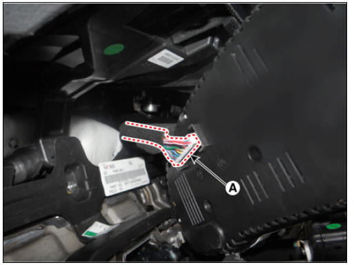
- Disconnect the connector (A) from the instrument cluster.
Installation
- Install in the reverse order of removal.
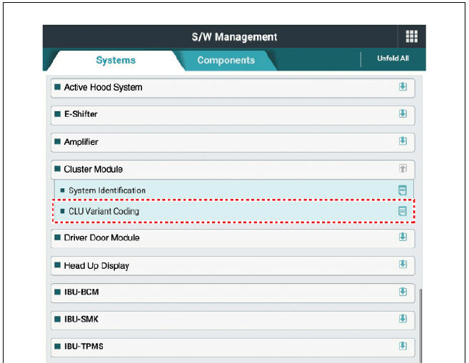
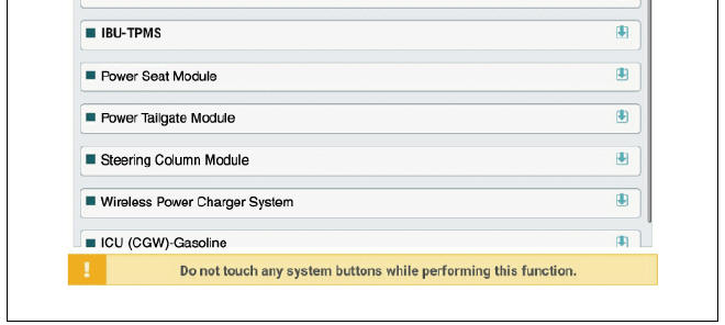
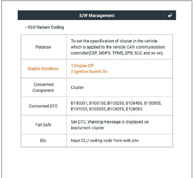
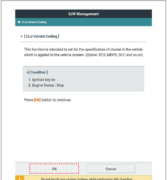
- After replacing the cluster with a new one, the "Variant Coding" procedure must be performed.
Inspection
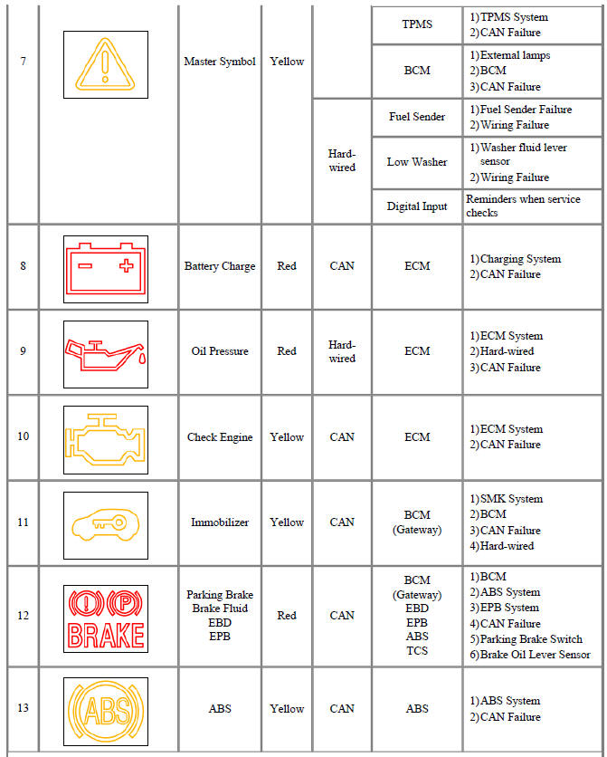
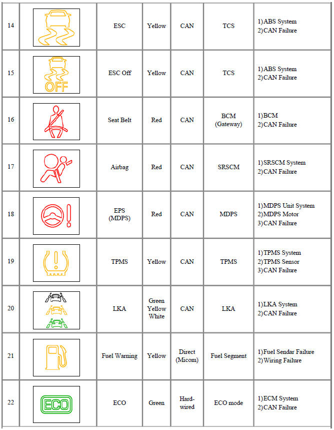
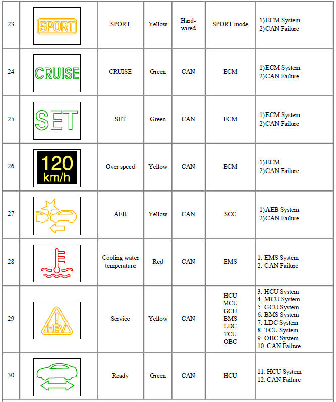
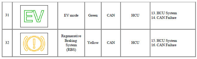
- Check point (Warning indicator)
Warning
- Fault conditions and normal operating conditions, refer to the owner's manual.
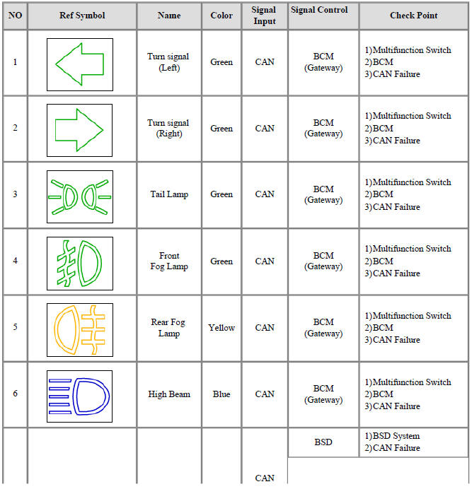
 Turn signal
(Left)
Turn signal
(Left) Turn signal
(Right)
Turn signal
(Right) Tail Lamp
 Front
Fog Lamp
Front
Fog Lamp Rear Fog
Lamp
Rear Fog
Lamp High Beam
 Master Symbol
 Battery Charge
 Oil Pressure
 Check Engine
 Immobilizer
 Parking Brake
Brake Fluid
EBD
EPB
Parking Brake
Brake Fluid
EBD
EPB ABS
ABS ESC
ESC ESC Off
 Seat Belt
 Airbag
 EPS
(MDPS)
EPS
(MDPS)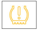 TPMS
TPMS LKA
LKA Fuel Warning
 ECO
ECO SPORT
SPORT CRUISE
 SET
SET Over speed
 AEB
AEB Cooling water
temperature
Cooling water
temperature Service
 Ready
Ready EV mode
 Regenerative
Braking
System
(RBS)
Regenerative
Braking
System
(RBS)
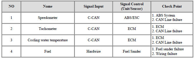
- Check point (Gauge)
Diagnosis with KDS
- In the body electrical system, failure can be quickly diagnosed by using
the vehicle diagnostic system (KDS).
The diagnostic system (KDS) provides the following information.
(1) Self diagnosis : Checking failure and code number (DTC)
(2) Current data : Checking the system input/output data state
(3) Actuation test : Checking the system operation condition
(4) Additional function : Controlling other features including system option setting and zero point adjustment
- Select the 'Car model' and the 'Cluster Module (CLU)' to be checked in order to check the vehicle with the tester
- Select the 'Current Data' menu to search the current state of the input/output data.
- To forcibly actuate the input value of the module to be checked, select option 'Actuation Test'
READ NEXT:
 Indicators And Gauges - Troubleshooting
Troubleshooting
Error Item:
Screen display
Failure
symptom:
LCD screen
does not turn
on
Inspection items:
Connector
attachments
Components
Detailed inspections:
Check the
connector
attachments
Check B+, IGN and
Integrated Memory System (IMS) / Description And Operation
Specifications
Memory Power Seat Unit
Memory Power Seat Switch
Integrated Memory System (IMS) / Components And Components Location
Memory power seat unit (PSM)
IMS control switch
Outside rear view mirror
IMS mirror control (D
SEE MORE:
Lane Keeping Assist (LKA)
Lane Keeping Assist is designed to help
detect lane markings (or road edges)
while driving over a certain speed. Lane
Keeping Assist will warn the driver if the
vehicle leaves the lane without using the
turn signal, or will automatically ass
Remote Smart Parking Assist malfunction
Remote Smart Parking Assist check
A: Check Parking Assist
Visit a nearby service center
When Remote Smart Parking Assist is
not working properly, the warning message
will appear on the infotainment
system screen. If the message appears
Categories
- Home
- KIA Niro EV, Hybrid - Second generation - (SG2) (2021-2024) - Owner's manual
- Kia Niro - First generation - (DE) (2017-2022) - Service and Repair Manual
- Contact Us