KIA Niro: Main High Voltage Battery Temperature Sensor
Kia Niro - First generation - (DE) (2017-2022) - Service and Repair Manual / Hybrid Control System / Main High Voltage Battery Temperature Sensor
Removal
Warning
- Be sure to read and follow the "General Safety Information and Caution" before doing any work related with the high voltage system. Failure to follow the safety instructions may result in serious electrical injuries.
- Be sure to read and follow the "High Voltage Shut-off Procedures" before doing any work related with the high voltage system. Failure to follow the safety instructions may result in serious electrical injuries.
Main High Voltage Battery Temperature Sensor
- Turn ignition switch OFF and disconnect the negative (-) battery cable.
- Shut off the high voltage.
(Refer to "High voltage Shut-off Procedures")
- Remove the power relay assembly (PRA).
(Refer to High Voltage Battery System - "Power Relay Assembly (PRA)")
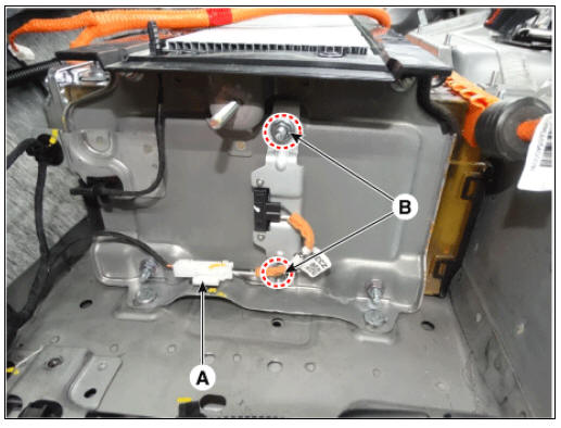
- Disconnect the runaway arresting device connector (A).
- Remove the runaway arresting device after loosening the mounting nuts (B).
Runaway Arresting Device (RAD) #1
Sub High Voltage Battery
- Turn ignition switch OFF and disconnect the negative (-) battery cable.
- Shut off the high voltage.
(Refer to "High voltage Shut-off Procedures")
- Remove the sub high voltage battery pack assembly.
(Refer to High Voltage Battery System - "Battery Pack Assembly")
- Remove the high voltage battery watertight case.
(Refer to High Voltage Battery System - "Case")
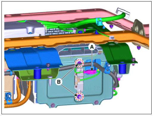
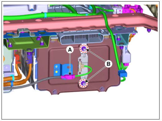
- Disconnect the runaway arresting device connector (A).
- Remove the runaway arresting device after loosening the mounting nuts (B).
Runaway Arresting Device (RAD) #2
Runaway Arresting Device (RAD) #3
Installation
Warning
- Be sure to read and follow the "General Safety Information and Caution" before doing any work related with the high voltage system. Failure to follow the safety instructions may result in serious electrical injuries.
- Be sure to read and follow the "High Voltage Shut-off Procedures" before doing any work related with the high voltage system. Failure to follow the safety instructions may result in serious electrical injuries.
Warning
Check that the VPD switch terminal (A) is facing down.
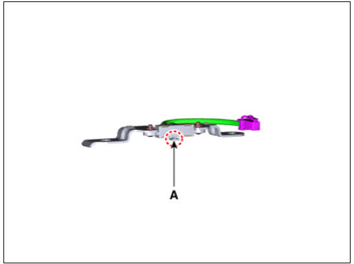
- Install in the reverse order of removal.
READ NEXT:
 Cooling Fan Description and operation | Cooling Fan Repair procedures
Component
Location
Cooling Fan #1
Cooling Fan #2
Main High Voltage Battery Cooling Duct (Inlet)
Main High Voltage Battery Cooling Duct (Outlet)
Sub High Voltage Battery Cooling Duct (Inlet)
Sub High Voltage Battery
SEE MORE:
Safety Plug Description and operation
Description
Safety Plug is installed on the rear side of the high voltage battery and it
can mechanically shut the
high voltage circuit off when servicing the high voltage system. (i.e. High
Voltage Battery, Power
Relay Assembly, HPCU, BMS ECU
Tire Pressure Monitoring System
Tire Pressure Monitoring System / Components And Components Location
BCM (TPMS)
TPMS Sensor (FL)
TPMS Sensor (RL)
TPMS Sensor (RR)
TPMS Sensor (FR)
Description
TREAD Lamp
Tire Under Inflation / Leak Warning.
Turn on c
Categories
- Home
- KIA Niro EV, Hybrid - Second generation - (SG2) (2021-2024) - Owner's manual
- Kia Niro - First generation - (DE) (2017-2022) - Service and Repair Manual
- Contact Us