KIA Niro: Measuring insulation resistance using an insulation tester
Warning
- Be sure to read and follow the "General Safety Information and Caution" before doing any work related with the high voltage system. Failure to follow the safety instructions may result in serious electrical injuries.
- Be sure to read and follow the "High Voltage Shut-off Procedures" before doing any work related with the high voltage system. Failure to follow the safety instructions may result in serious electrical injuries.
- Shut off the high voltage circuit.
(Refer to Hybrid Control System - "High Voltage Shut-off Procedures")
- Remove the rear seat cushion.
(Refer to Body - "Rear Seat Assembly")
- Remove the rear door scuff trim.
(Refer to Body - "Door Scuff Trim")
- Remove the inlet cooling duct..
(Refer to High Voltage Battery Cooling System - "Cooling Duct")
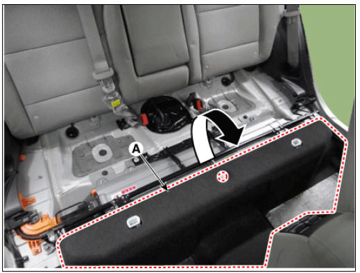
- Open the high voltage battery cushion (A) in the direction of an arrow.
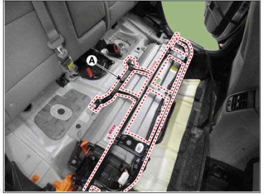
- Remove the upper frame (A) after loosening the mounting bolts and nuts.
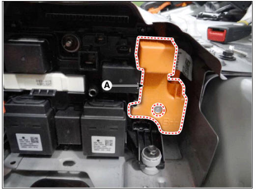
- Remove the high voltage cable cover (A) after loosening the mounting bolt.
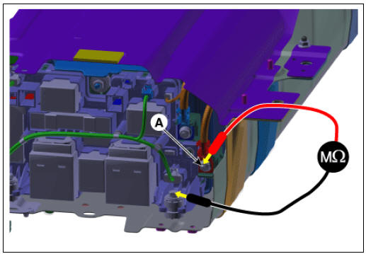
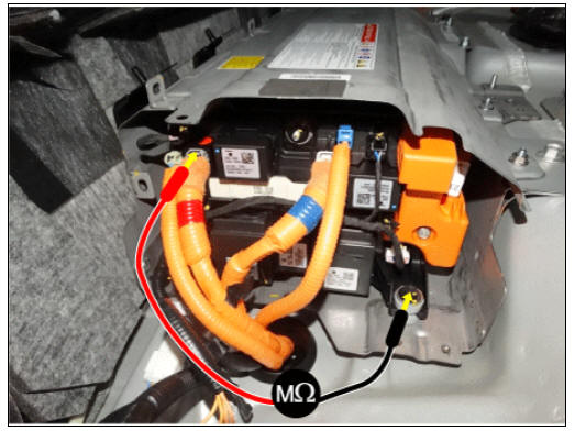
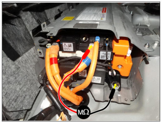
- Connect the insulation tester (-) terminal (A) to the battery system case (or ground).
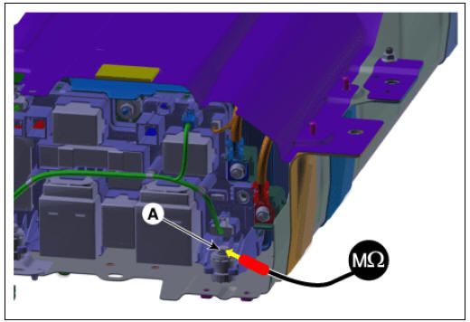
- Connect the insulation tester (+) terminal to the high voltage battery (+) and (-). Measure the resistance.
Measure the isolation resistance on the power relay assembly high voltage power terminal (+))
(1) Connect the insulation tester (+) terminal to the (+) PRA high voltage power terminal (A).
(2) Supply 500V through the insulation tester and wait one minute to measure the stable resistance.
(3) Check the isolation resistance.
Normal insulation resistance range : Above 1.0 MΩ (20ºC (68ºF))
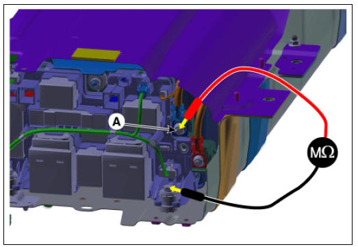
Measure the isolation resistance on the power relay assembly high voltage power terminal (-)
- Connect the insulation tester (+) terminal to the (-) PRA high voltage power terminal (B).
- Supply 500V through the insulation tester and wait one minute to measure the stable resistance.
- Check the isolation resistance.
Normal insulation resistance range : Above 1.0 MΩ (20ºC (68ºF))
Measure the isolation resistance on the power relay assembly inverter power terminal (+)
Warning
When measuring the insulated resistance on each PRA inverter, use a
contact pin to prevent damage on the connector
and for more accurate measurement.
- Connect the insulation tester (+) terminal to the (+) PRA inverter power terminal (A).
- Supply 500V through the insulation tester and wait one minute to measure the stable resistance.
- Check the isolation resistance.
Normal insulation resistance range : Above 1.0 MΩ (20ºC (68ºF))
Measure the isolation resistance on the power relay assembly inverter power terminal (-)
Warning
When measuring the insulated resistance on each PRA inverter, use a
contact pin to prevent damage on the connector
and for more accurate measurement.
- Connect the insulation tester (+) terminal to the (-) PRA inverter power terminal (B).
- Supply 500V through the insulation tester and wait one minute to measure the stable resistance.
- Check the isolation resistance.
Normal insulation resistance range : Above 1.0 MΩ (20ºC (68ºF))
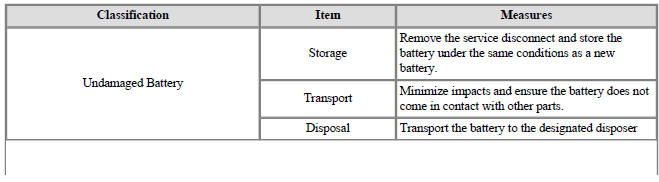
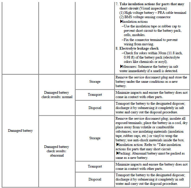
Handling Guide for Storing, Transporting, and Disposing of High Voltage Battery Systems
- High voltage battery system handling process
- Defective high voltage battery system handling / Inspection
READ NEXT:
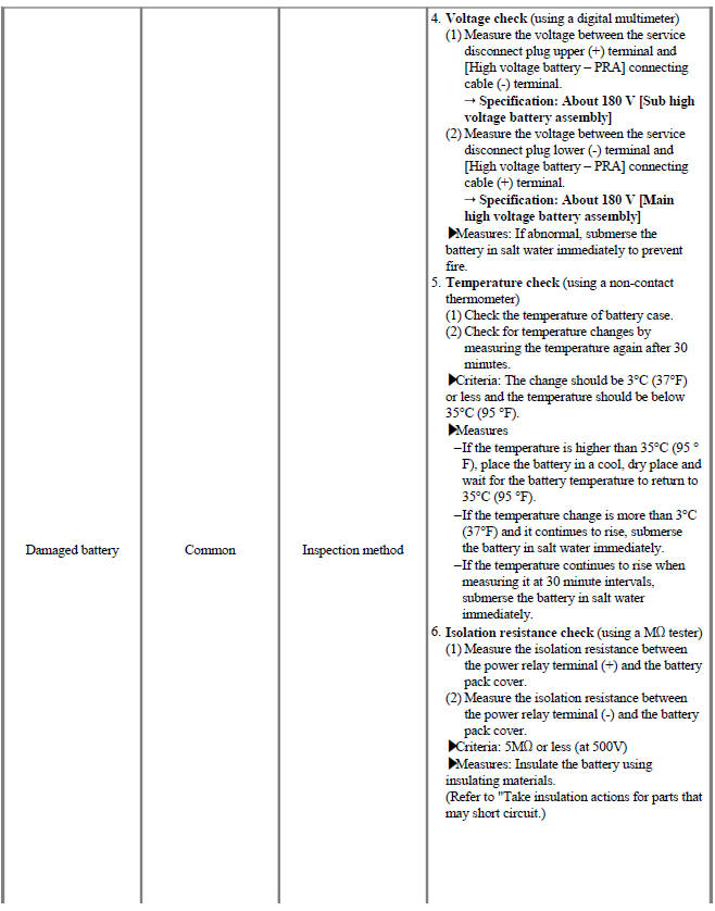
 Voltage Check
Warning
Be sure to read and follow the "General Safety Information and
Caution" before doing any work related with the high
voltage system. Failure to follow the safety instructions may result in serious
electrical injuries.
Measu
Service Highlight / Inspection Mode Procedures
Procedure for entering engine forced activation mode
If the engine needs to be running constantly while the vehicle is stopped to
inspect emission gas or
perform maintenance on the vehicle, follow below procedure to enter engine
forced activati
SEE MORE:
Engine Mounting Repair Procedures
Engine Mounting Components and components location
Transaxle mounting bracket
Roll rod bracket
Engine mounting bracket
Engine mounting support bracket
Engine Mounting Repair Procedures
Removal and
Installation
Engine Mounting Brac
Headlamps Description and operation | Lighting System / Headlamps Repair Procedures
Description
BI-FUNCTION
Definition
A headlamp with integrated functions of high and low beam
The light is controlled by rotating the shield inserted to the lens. (A solenoid is adopted.)
Structure and mechanism
Categories
- Home
- KIA Niro EV, Hybrid - Second generation - (SG2) (2021-2024) - Owner's manual
- Kia Niro - First generation - (DE) (2017-2022) - Service and Repair Manual
- Contact Us