KIA Niro: Motor compartment fuse panel (Kia Niro EV)
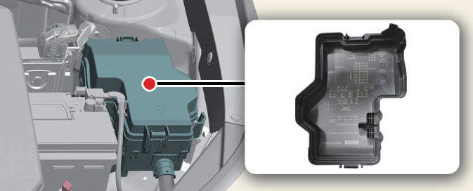
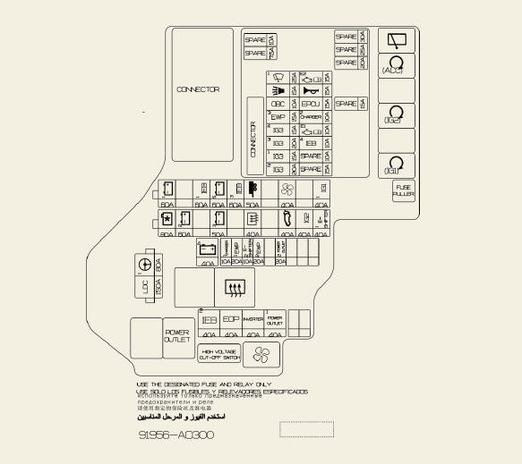
Circuit (P/R Junction Block)
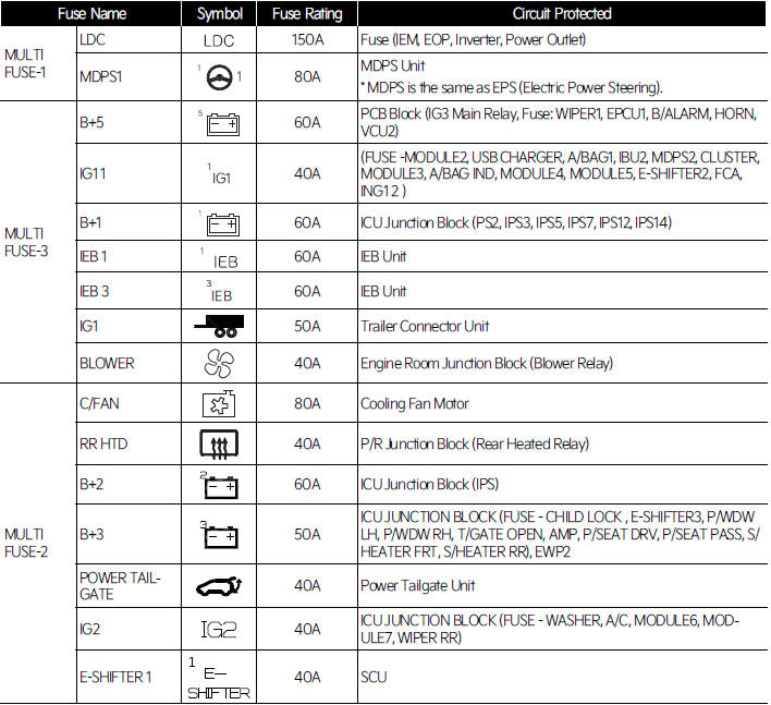
Fuse Name/ Symbol/ Fuse Rating/ Circuit Protected
MULTI FUSE-1
- LDC/
 / 150A/ Fuse (IEM, EOP,
Inverter, Power Outlet)
 - MDPS1/
 / 80A/
MDPS Unit
* MDPS is the same as EPS (Electric Power Steering).
MULTI FUSE-3
- B+5/
 / 60A/ PCB Block (IG3
Main Relay, Fuse: WIPER1, EPCU1, B/ALARM, HORN,
VCU2)
 - IG1/
 / 40A/
(FUSE -MODULE2, USB CHARGER, A/BAG1, IBU2, MDPS2, CLUSTER,
MODULE3, A/BAG IND, MODULE4, MODULE5, E-SHIFTER2, FCA,
ING1 2 )
 - B+1/
 / 60A/ ICU Junction
Block (PS2, IPS3, IPS5, IPS7, IPS12, IPS14)
 - IEB 1/
 / 60A/ IEB Unit
 - IEB 3/
 / 60A/ IEB Unit
 - IG1/
 / 50A/ Trailer
Connector Unit
 - BLOWER/
 / 40A/ Engine Room
Junction Block (Blower Relay)
MULTI FUSE-2
- C/FAN/
 / 80A/ Cooling Fan
Motor
 - RR HTD/
 / 40A/ P/R Junction
Block (Rear Heated Relay)
 - B+2/
 / 60A/ ICU Junction
Block (IPS)
 - B+3/
 / 50A/
ICU JUNCTION BLOCK (FUSE - CHILD LOCK , E-SHIFTER3, P/WDW
LH, P/WDW RH, T/GATE OPEN, AMP, P/SEAT DRV, P/SEAT PASS, S/
HEATER FRT, S/HEATER RR), EWP2
 - POWER TAILGATE/
 /
40A/ Power Tailgate Unit
 - IG2/
 / 40A/ ICU
JUNCTION BLOCK (FUSE - WASHER, A/C, MODULE6, MODULE7,
WIPER RR)
 - E-SHIFTER 1/
 / 40A/ SCU
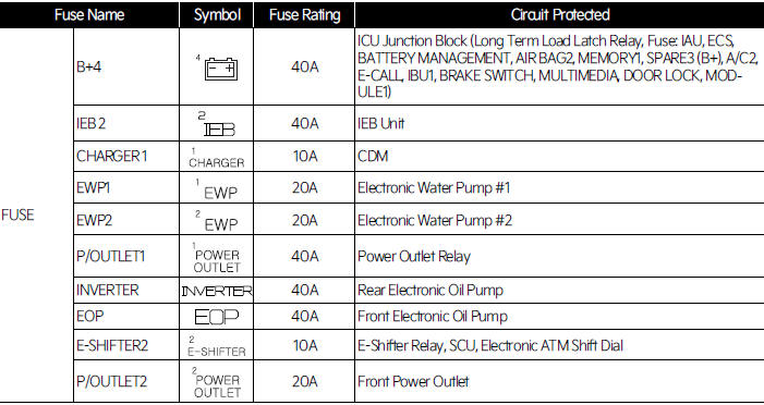
FUSE
- B+4/
 / 40A/
ICU Junction Block (Long Term Load Latch Relay, Fuse: IAU, ECS,
BATTERY MANAGEMENT, AIR BAG2, MEMORY1, SPARE3 (B+), A/C2,
E-CALL, IBU1, BRAKE SWITCH, MULTIMEDIA, DOOR LOCK, MODULE1)
 - IEB 2/
 / 40A/ IEB Unit
 - CHARGER 1/
 / 10A/ CDM
 - EWP1/
 / 20A/ Electronic
Water Pump #1
 - EWP2/
 / 20A/
Electronic Water Pump #2
 - P/OUTLET1/
 / 40A/
Power Outlet Relay
 - INVERTER/
 / 40A/ Rear
Electronic Oil Pump
 - EOP/
 / 40A/ Front Electronic
Oil Pump
 - E-SHIFTER2/
 / 10A/ E-Shifter
Relay, SCU, Electronic ATM Shift Dial
 - P/OUTLET2/
 / 20A/ Front
Power Outlet
PCB Block
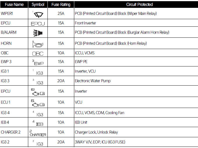
Fuse Name/ Symbol/ Fuse Rating/ Circuit Protected
WIPER1/ / 25A/ PCB (Printed
Circuit Board) Block (Wiper Main Relay)
EPCU/ / 15A/ Front Inverter
B/ALARM/ / 15A / PCB (Printed
Circuit Board) Block (Burglar Alarm Horn Relay)
HORN/ / 15A/ PCB (Printed
Circuit Board) Block (Horn Relay)
OBC / / 10A/ ICCU, VCMS
EWP 3/ / 15A/ EWP PE
IG3 1/ / 15A /Inverter, VCU
IG3 3/ / 20A/ Electronic
Water Pump
EPCU/ / 15A/ Inverter
ECU 1/ / 10A/ VCU
IG3 4/ / 15A/ ICCU, VCMS, CDM,
Cooling Fan
IEB 4/ / 10A/ IEB Unit
CHARGER 2/ / 10A/ Charger Lock,
Unlock Relay
IG3 2/ / 20A/ 3WAY V/V, EOP,
ICU (IG3 FUSE)
Relay
Refer to the following table for the relay type.
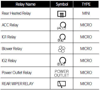
Rear Heated Relay  MINI
MINI
ACC Relay MICRO
MICRO
IG1 Relay MICRO
MICRO
Blower Relay MICRO
MICRO
IG2 Relay  MICRO
MICRO
Power Outlet Relay  MICRO
MICRO
REAR WIPER RELAY  MICRO
MICRO
READ NEXT:
 Bulb replacement
precautions
Turn off the vehicle at a safe place,
firmly apply the side brake and take out
the battery's negative (-) terminal. Use
only the bulbs of the specified wattage.
Lamp part malfunction due to
network failure
Lamp part malfunction may be cause
 Light position
Light position
(Front)
Head lamp - Type A
Head lamp - Type B
Front fog lamp
Headlamp (Low) (LED type)
Headlamp (Low/High) (Bulb type)
Headlamp (Low/High) (LED type)
Front turn signal lamp (Bulb type)
Day time running lamp
SEE MORE:
 Shift dial SBW type of DCT warning messages
Message/ Content
A: Steep grade! Press brake pedal
To hold the vehicle on an incline use the foot brake or the
parking brake.
When in stop-and-go traffic on an incline, allow a gap to form
ahead of you before moving the vehicle forward
 Power tailgate
Operating the power tailgate
Operation
Press the power tailgate open/close
button inside the vehicle or with the
smart key for 1 second. The power
tailgate opens with a warning sound.
Press and hold the power tailgate
open/clos
Categories
- Home
- KIA Niro EV, Hybrid - Second generation - (SG2) (2021-2024) - Owner's manual
- Kia Niro - First generation - (DE) (2017-2022) - Service and Repair Manual
- Contact Us
