KIA Niro: Power Window Motor
Power Window Motor Components and components location
Power Window Motor Schematic diagrams
Power Window Motor Repair procedures
Inspection
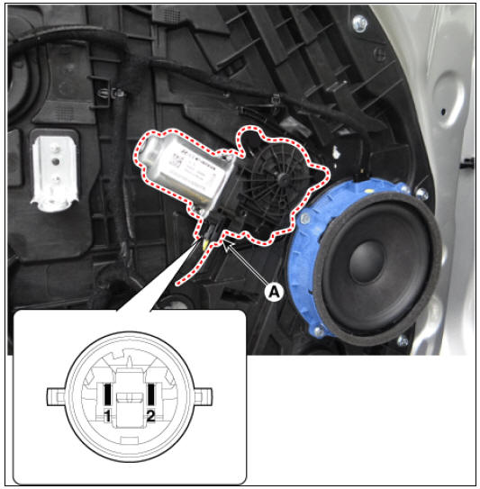
Front Power Window Motor
- Remove the front door trim.
(Refer to Body - "Front Door Trim")
- Disconnect the motor connector (A) from the motor.
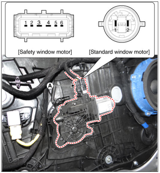
- Connect the terminal No.2 and No.1 to battery voltage (12V) and check that the motor operates smoothly when connecting the terminals below.
Safety Window Motor
- Connect the motor terminals directly to battery voltage (12V) and check that the motor operates smoothly. Next, reverse the polarity and check that the motor operates smoothly in the reverse direction. If the operation is abnormal, replace the motor.
Standard Window Motor
Rear Power Window Motor
- Remove the rear door trim.
(Refer to Body - "Rear Door Trim")
- Disconnect the motor connector (A) from the motor.
- Connect the motor terminals No.1 and No.2 directly to battery voltage
(12V) and check that the
motor operates smoothly.
If the operation is abnormal, replace the motor.
Removal
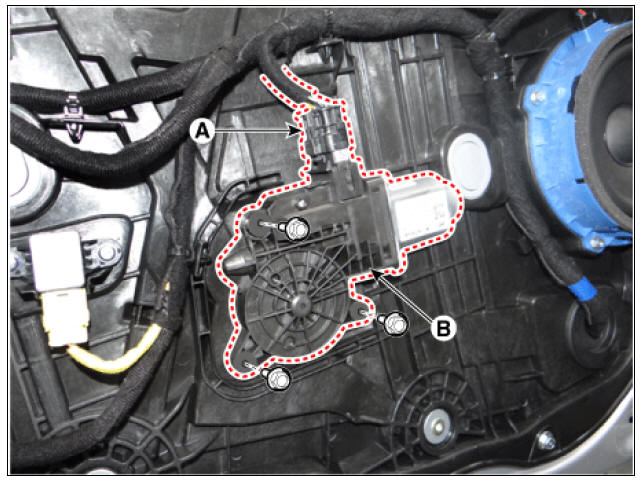
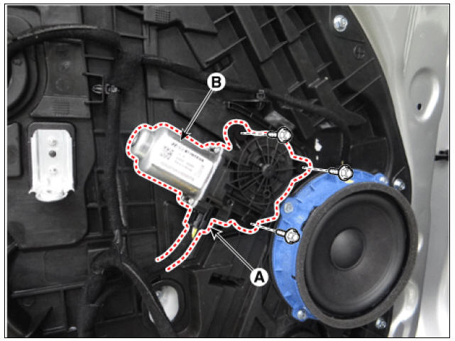
Front Power Window Motor
- Remove the front door trim.
(Refer to Body - "Front Door Trim")
- After disconnecting the motor connector (A), remove the power window motor (B) by loosening the bolts.
Rear Power Window Motor
- Remove the rear door trim.
(Refer to Body - "Rear Door Trim")
- After disconnecting the motor connector (A), remove the power window motor (B) by loosening the bolts.
Installation
- Install in the reverse order of removal.
READ NEXT:
 Power Window Switch
Power Window Switch Components and components location
Power Window Main Switch
Non-IMS type
IMS type (DDM : Driver Door Module)
Assist Power Window Switch
Non-IMS type
IMS type (ADM : Assist Door Module)
Rear Glass Defogger
Rear Glass Defogger / Components And Components Location
Body control module (BCM)
Rear glass defogger switch
Rear glass defogger
Rear Glass Defogger Printed Heater Repair
Inspection
Warning
Wrap tin foil around the end of the volt
SEE MORE:
Checking the inverter coolant level (HEV)
If frequent additions are required, we
recommend that the system be
inspected by a professional workshop.
Kia recommends to visit an authorized
Kia dealer/service partner.
The inverter coolant level should be in
between MAX and MIN when the
Door Scuff Trim | Cowl Side Trim
Front pillar trim
Front door scuff trim
Center pillar upper trim
Rear door scuff trim
Cowl side trim
Center pillar lower trim
Rear pillar trim
Door Scuff Trim
Component Location
Front door scuff trim
Categories
- Home
- KIA Niro EV, Hybrid - Second generation - (SG2) (2021-2024) - Owner's manual
- Kia Niro - First generation - (DE) (2017-2022) - Service and Repair Manual
- Contact Us