KIA Niro: Power Windows / Description And Operation
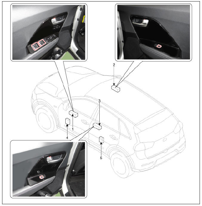
Power Windows / Components And Components Location

- Driver power window switch
- Assist power window switch
- Rear power window switch
- Front window motor
- Rear window motor
Power Windows / Description And Operation
Power Window Safety Function
When the driver or passenger power window auto-up switch is operated, the power window safety function is activated.
- Safety function enable conditions
When the window is closing and restriction 100N (using the 10N/mm spring) has been detect causing the motor to slow down, the window is reversed.
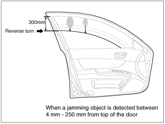
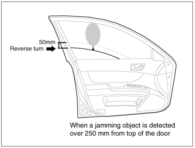
- Window reversing distance (except while holding the Auto-Up switch).
- When jamming (resistance) is detected between 4 - 250mm from the top of
the door.
→ the window is lowered to 300mm from the top of the door as shown below.

- When jamming (resistance) is detected from more than 250mm from the top
of the door.
→ the window is lowred to the lowest position plus an additional 50mm from the lowest position.

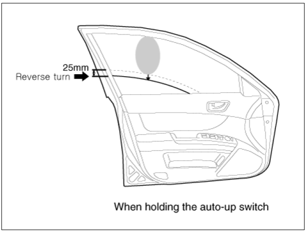
- Window reversing distance (while holding the Auto-Up switch)
- When jamming (resistance) is detected while holding (actuating) the
auto-up switch.
→ Window moves downward by 25mm from jamming position
- Auto-up function is not available for 5 seconds after the above
operation.
→ When pulling the auto-up switch, the manual-up function is activated (no safety function).

- The area with the safety function is not applied
Safety function is not available within the 4mm range from the top of the window frame.
How to initialize the safety power window
- Initializing of Battery Connection
When the battery power is removed for more than 5 minutes, the safety power window switch needs to be re-initialized.
(1) Power window operation before initializing
- Manual-Up/Down function is available
- Auto-Up/Down function is not available (Only up/down available while holding the switch)
(2) Initialization
With the window in the FULL OPEN position, press and hold the UP switch position until it fully closes and hold switch for an additional 0.2 seconds.
(Procedure will fail if starting initializing with the window in closed position)
(3) If initializing procedure while the safety system still in jamming status, the safety function is not available.
(4) The window safety motor uses a hall type sensor that is used to verify the position and direction of the motor, the safety module detects the uppermost (full closed)position of the window and sets the position as "0" or full closed.
(5) Deinitialization
The window safety module is deinitialized if the conditions listed below occur. Auto-Up and Safety function are deactivated.
Deinitialization conditions
- Repeating window downward movement 15 or more times in a row.
- Power supply is suspended while the motor is in operation.
- Driver door opens, IGN Off with the window glass positioned in Hard Stop -> IGN On within 2 seconds -> within 5 seconds with IGN On, entering manual down switch signal 3 times -> Deinitialization completed (if power is not on in 2 seconds, or the operation to be performed in 5 seconds, the deinitialization process shall be repeated from the beginning.)
- Initializing of fail safe mode
System includes motor overheating prevention feature, avoid overrunning/overheating of the window motor.(EEPROM data is stored in safety module)
(1) If the window moved by force and motor has a problem, power window switch could enter in fail safe mode for user's safety.
(2) Power window operation in fail mode
- Auto/Manual-Down function is available
- Auto/Manual-Up function is not available (When Auto/Manual-up is operated, window rises by 20mm and stops moving.)
READ NEXT:
 Power Window Motor
Power Window Motor Components and components location
Power Window Motor Schematic diagrams
Power Window Motor Repair procedures
Inspection
Front Power Window Motor
Remove the front door trim.
(Refer to Body - "Front Door Trim&
 Power Window Switch
Power Window Switch Components and components location
Power Window Main Switch
Non-IMS type
IMS type (DDM : Driver Door Module)
Assist Power Window Switch
Non-IMS type
IMS type (ADM : Assist Door Module)
 Rear Glass Defogger
Rear Glass Defogger / Components And Components Location
Body control module (BCM)
Rear glass defogger switch
Rear glass defogger
Rear Glass Defogger Printed Heater Repair
Inspection
Warning
Wrap tin foil around the end of the volt
SEE MORE:
 Clutch Actuator Motor
Remove the under cover.
(Refer to Engine Mechanical System - "Engine Room Under Cover")
Remove the front wheel guard (LH).
(Refer to Body - "Front Wheel Guard")
Disconect the clutch actuator connector (A).
Motor
 Battery Terminal | Battery Condition
Check the battery voltage and status using the battery tester.
Battery Terminal
Move back and forth to check that the battery terminals (A) are loose or corroded.If the terminals are corroded, clean them.
If battery positive connect
Categories
- Home
- KIA Niro EV, Hybrid - Second generation - (SG2) (2021-2024) - Owner's manual
- Kia Niro - First generation - (DE) (2017-2022) - Service and Repair Manual
- Contact Us
