KIA Niro: Stop Lamp Switch
Stop Lamp Switch Components and components location
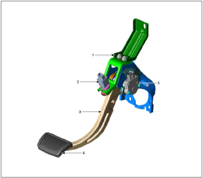
- Brake pedal member assembly
- Stop lamp switch
- Brake pedal arm
- Brake pedal pad
- Brake pedal stroke sensor
Operation
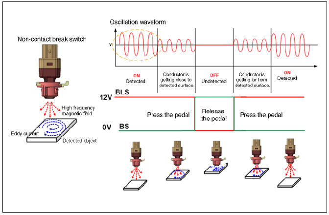
Operation principle of inductive non-contact switch
- Use the high frequency magnetic field and the induced current that are generated by oscillation (to approved voltage) of coil in switch.
- The eddy current is generated on surface of metal by self inductance effect if there is metal in high frequency magnetic field.
- The eddy current that is generated attenuates the high frequency magnetic field as much as amount of generated by disturbing the switch's magnetic flux.
- ON-OFF by judging whether high voltage magnetic field is attenuates or not(calculate the voltage difference by length between metal and coil)
Schematic Diagram
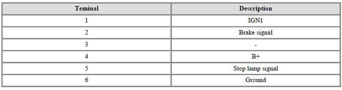
Terminal function
Stop Lamp Switch - Troubleshooting
- Part diagnosis
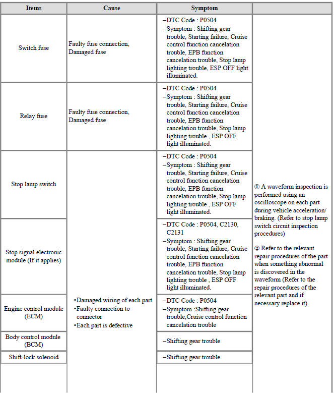
Items:
Switch fuse
Cause:
Faulty fuse connection, Damaged fuse
Symptom:
- DTC Code : P0504
- Symptom : Shifting gear trouble, Starting failure, Cruise control function cancelation trouble, EPB function cancelation trouble, Stop lamp lighting trouble, ESP OFF light illuminated.
Items:
Relay fuse
Cause:
Faulty fuse connection, Damaged fuse
Symptom:
- DTC Code : P0504
- Symptom : Shifting gear trouble, Starting failure, Cruise control function cancelation trouble, EPB function cancelation trouble, Stop lamp lighting trouble , ESP OFF light illuminated.
Items:
Stop lamp switch
Cause:
- Damaged wiring of each part
- Faulty connection to connector
- Each part is defective
Symptom:
- DTC Code : P0504
- Symptom : Shifting gear trouble, Starting failure, Cruise control function cancelation trouble, EPB function cancelation trouble, Stop lamp lighting trouble , ESP OFF light illuminated.
Items:
Stop signal electronic module (If it applies)
Cause:
- Damaged wiring of each part
- Faulty connection to connector
- Each part is defective
Symptom:
- DTC Code : P0504, C2130, C2131
- Symptom : Shifting gear trouble, Starting failure, Cruise control function cancelation trouble, EPB function cancelation trouble, Stop lamp lighting trouble , ESP OFF light illuminated.
Items:
Engine control module (ECM)
Cause:
- Damaged wiring of each part
- Faulty connection to connector
- Each part is defective
Symptom:
- DTC Code : P0504
- Symptom :Shifting gear trouble,Cruise control function cancelation trouble
Items:
Body control module (BCM)
Cause:
- Damaged wiring of each part
- Faulty connection to connector
- Each part is defective
Symptom:
- Shifting gear trouble
Items:
Shift-lock solenoid
Cause:
- Damaged wiring of each part
- Faulty connection to connector
- Each part is defective
Symptom:
- Shifting gear trouble
Items:
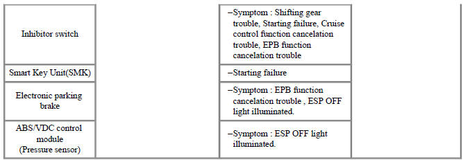
Inhibitor switch
Cause:
- Damaged wiring of each part
- Faulty connection to connector
- Each part is defective
Symptom:
- Symptom : Shifting gear trouble, Starting failure, Cruise control function cancelation trouble, EPB function cancelation trouble
Items:
Smart Key Unit(SMK)
Cause:
- Damaged wiring of each part
- Faulty connection to connector
- Each part is defective
Symptom:
- Starting failure
Items:
Electronic parking brake
Cause:
- Damaged wiring of each part
- Faulty connection to connector
- Each part is defective
Symptom:
- Symptom : EPB function cancelation trouble , ESP OFF light illuminated.
Items:
ABS/VDC control module (Pressure sensor)
Cause:
- Damaged wiring of each part
- Faulty connection to connector
- Each part is defective
Symptom:
- Symptom : ESP OFF light illuminated.
- A waveform inspection is performed using an oscilloscope on each part during vehicle acceleration/ braking. (Refer to stop lamp switch circuit inspection procedures)
- Refer to the relevant repair procedures of the part when something abnormal is discovered in the waveform (Refer to the repair procedures of the relevant part and if necessary replace it)
- Symptom diagnosis
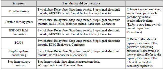
Symptom:
Trouble starting
Part that could be the cause:
Switch fuse, Relay fuse, Stop lamp switch, Stop signal electronic module, ABS/VDC control module, Each wire, Connector
Symptom:
Trouble shifting gears
Part that could be the cause:
Switch fuse, Relay fuse, Stop lamp switch, Stop signal electronic module, BCM, ECM, Inhibitor switch, Each wire, Connector
Symptom:
ESP OFF light illuminated
Part that could be the cause:
Switch fuse, Relay fuse, Stop lamp switch, Stop signal electronic module, ABS/VDC control module, Each wire, Connector
Symptom:
P0504
Part that could be the cause:
Switch fuse, Relay fuse, Stop lamp switch, Stop signal electronic module, ECM, Each wire, Connector
Symptom:
Stop lamp does notworking
Part that could be the cause:
Switch fuse, Relay fuse, Stop lamp switch, Stop signal electronic module, Wire/Connector disconnected
Symptom:
Stop lamp always turns on
Part that could be the cause:
Stop lamp switch, Stop signal electronic module, Wiring short circuit, Damaged fuse
- Inspect waveform using
an oscilloscope on each
part during vehicle
acceleration/braking.
(Refer to stop lamp switch circuit inspection Procedures)
- Refer to the relevant repair procedures of the part when something abnormal is discovered in the waveform (Refer to the repair procedures of the relevant part and if necessary replace it)
3. Stop lamp switch system diagnosis
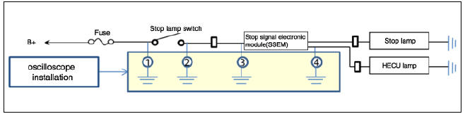
SSEM : Stop Signal Electronic Module
- Refer to DTC guide when the related DTC codes are displayed.
READ NEXT:
 Stop Lamp Switch Repair procedures
Removal
Turn ignition switch OFF and disconnect the negative (-) battery
terminal.
Remove the crash pad lower panel.
(Refer to Body - "Crash Pad")
Remove the knee air bag.
(Refer to Restraint - "Knee Airbag(KAB) Module&q
SEE MORE:
Rear View Monitor malfunction and limitations
Rear View Monitor malfunction
When Rear View Monitor is not working
properly, or the screen flickers, or the
camera image does not display properly,
Kia recommends visiting an authorized
Kia dealer/service partner.
Limitations of Rear View Moni
Brake Actuation Unit Repair procedures
Brake Actuation Unit Components and components location
Warning
IBAU(Intergrated Brake Actuation Unit) must not be disassembled.
Integrated Brake Actuation Unit (IBAU) ECU
Reservoir
Pedal Simulator
Integrated Brake Actuation Unit (IBA
Categories
- Home
- KIA Niro EV, Hybrid - Second generation - (SG2) (2021-2024) - Owner's manual
- Kia Niro - First generation - (DE) (2017-2022) - Service and Repair Manual
- Contact Us