KIA Niro: TPMS Receiver Repair procedures
Kia Niro - First generation - (DE) (2017-2022) - Service and Repair Manual / Suspension System / Tire Pressure Monitoring System / TPMS Receiver Repair procedures
Removal
- Disconnect the battery negative cable.
- Remove the glove box.
(Refer to Body - "Glove Box Housing")
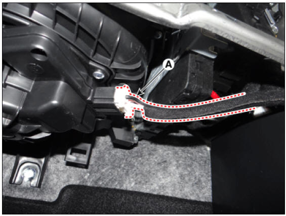
- Disconnect the blower motor connector (A).
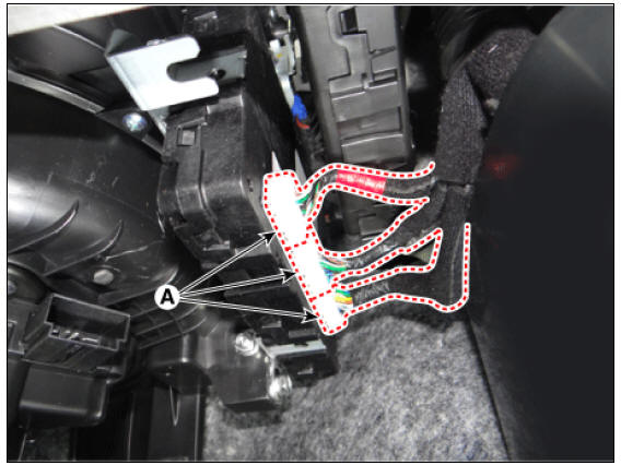
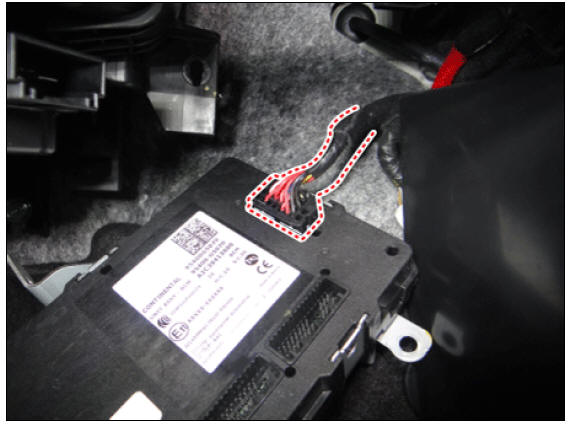
- Disconnect the body control module (BCM) connector (A).
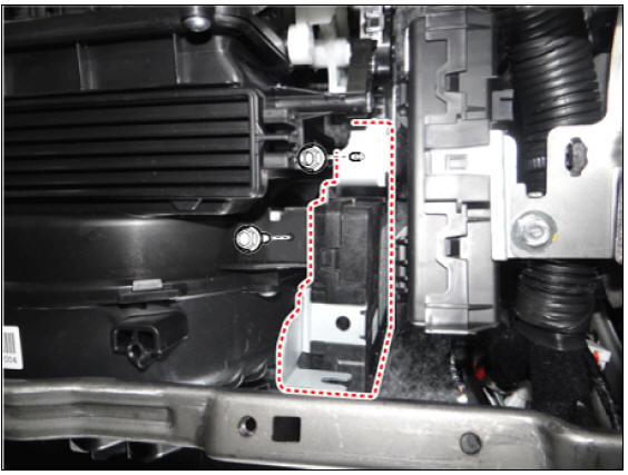
- Loosen the body control module bolt and nut.
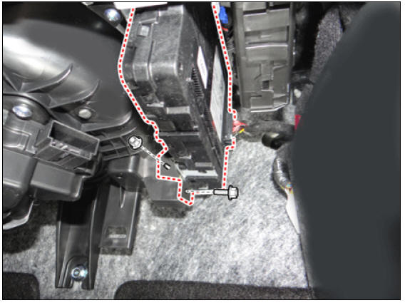
- Disconnect the connector and then remove the body control module.
- Install in the reverse order of removal.
Warning
After replacing the receiver, learn by using self-diagnostic device (KDS/GDS).
Diagnosis procedure by using diagnostic device
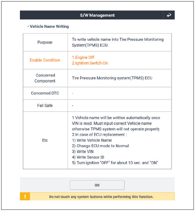
Vehicle Name Writing Method
- Connect self-diagnosis connector (16pins) located under the driver side crash pad to self-diagnosis device, and then turn the self-diagnosis device after key is ON.
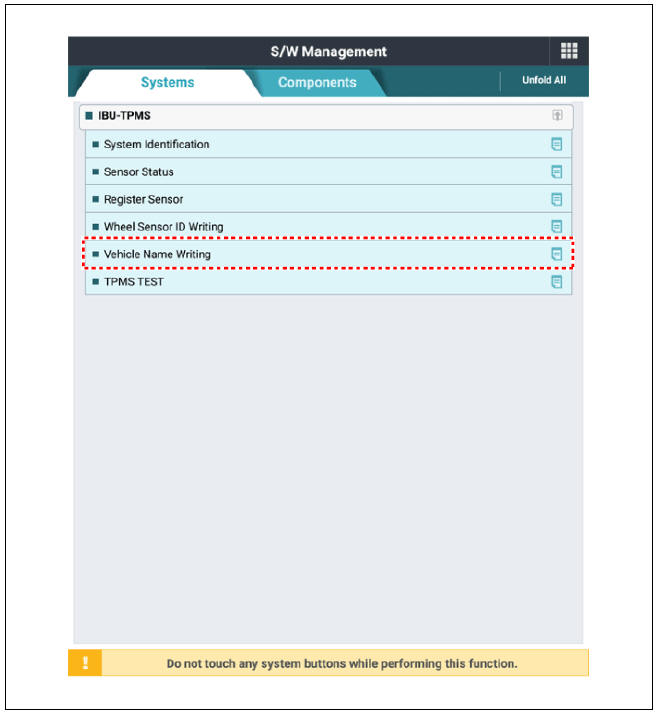
- Select the "vehicle model" and "IBU-TPMS" on KDS vehicle selection screen.
- Select the "Vehicle Name Writing" on KDS screen, then select OK.
- Proceed with the test according to the screen instructions.
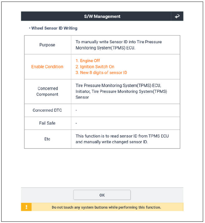
Wheel Sensor ID Writing Method
- Connect self-diagnosis connector (16pins) located under the driver side crash pad to self-diagnosis device, and then turn the self-diagnosis device after key is ON.
- Select the "vehicle model" and "IBU-TPMS" on KDS vehicle selection screen.
- Select the "Wheel Sensor ID Writing" on KDS screen, then select OK.
- Proceed with the test according to the screen instructions.

READ NEXT:
 Steering System / Repair Procedures
Service Data
Tightening Torques
Service Adjustment procedure
Steering Wheel Play Inspection
Turn the steering wheel so that the front wheels are facing straight
ahead.
Measure the distance that the steering wheel can be turned wit
Electric Power Steering
Description
MDPS (Motor Driven Power Steering) system uses an electric motor to assist
the steering force and it
is an engine operation independent steering system.
MDPS control module controls the motor operation according to information
re
SEE MORE:
Front Brake
Inspection
Check the pads for excessive wear, discs for run out and wear, and calipers
for fluid leakage.
Front brake disc thickness check
Check the brake pads for wear and fade.
Check the brake disc for damage and cracks.
Remove all rust
Curtain Airbag (CAB)
Description
Curtain airbags are installed inside the headliner (LH and RH) and protect
the driver and passenger
from danger when side crash occurs. The SRSCM determines deployment of curtain
airbag by using
side impact sensor (SIS) signal.
Wa
Categories
- Home
- KIA Niro EV, Hybrid - Second generation - (SG2) (2021-2024) - Owner's manual
- Kia Niro - First generation - (DE) (2017-2022) - Service and Repair Manual
- Contact Us