KIA Niro: AVN System / Description And Operation
Kia Niro - First generation - (DE) (2017-2022) - Service and Repair Manual / Body Electrical System / AVN System / AVN System / Description And Operation
AVN System / Components And Components Location
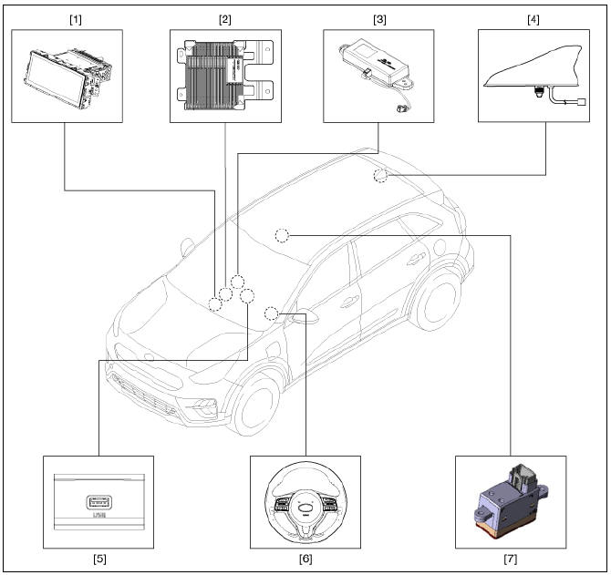
- AVN head unit
- External amplifier
- Crash pad LTE antenna
- Roof LTE antenna
- Multimedia jack
- Steering wheel remote control (SWRC)
- Hands-free mic (Built-in overhead console)
Description
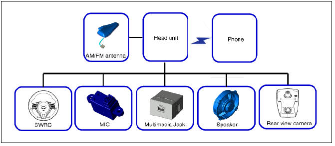
The system is basically composed of a keyboard for the operation of combined function, LCD monitor, a head unit with Bluetooth handsfree calling, voice recognition and navigation, music amplifier and the media unit that connects with other external devices.
System Block Diagram
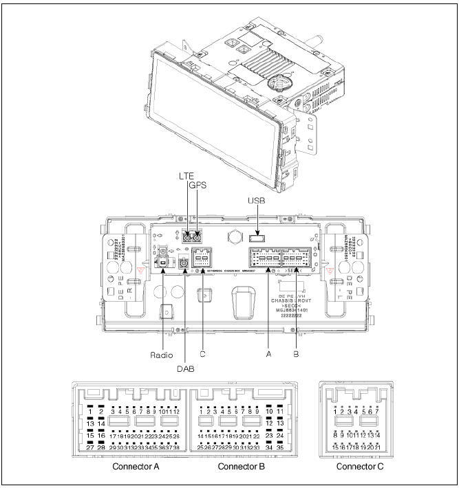
AVN(Audio Video Navigation) head unit Components and components location
Display Audio Head Unit
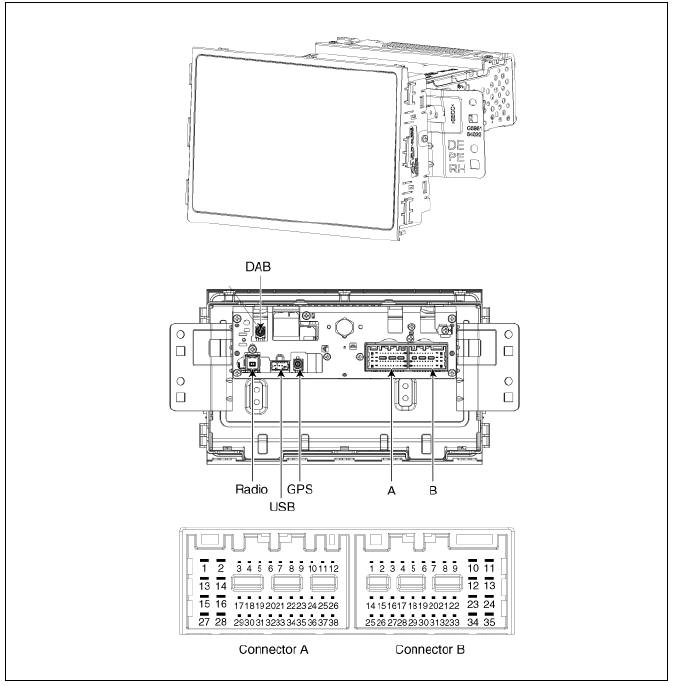
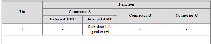
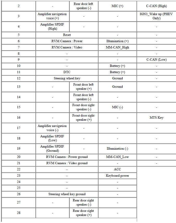
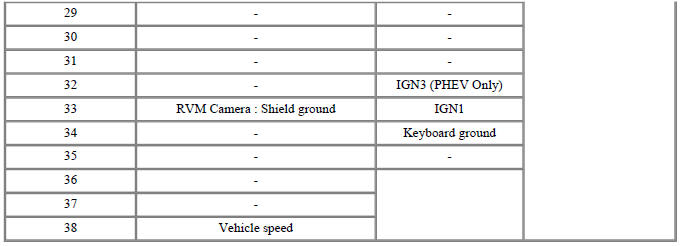
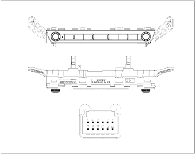
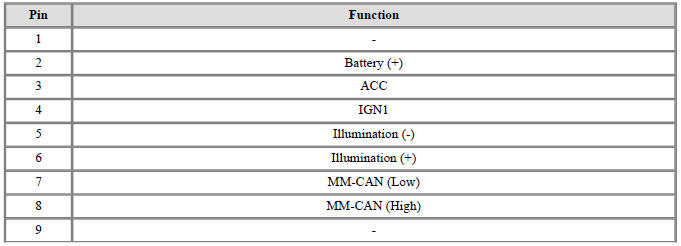
Connector Pin Information

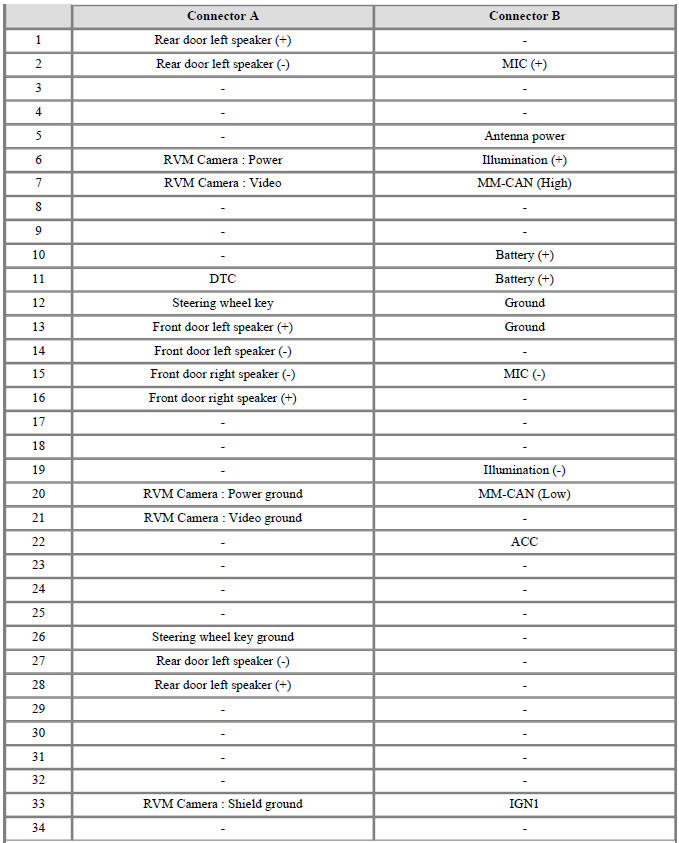
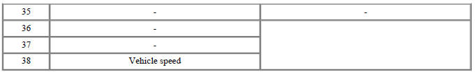
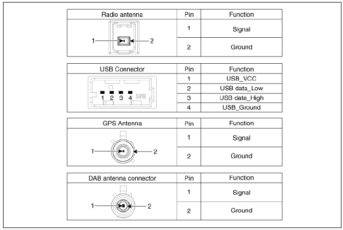
AVN Head Unit
AVN(Audio Video Navigation) head unit Repair procedures
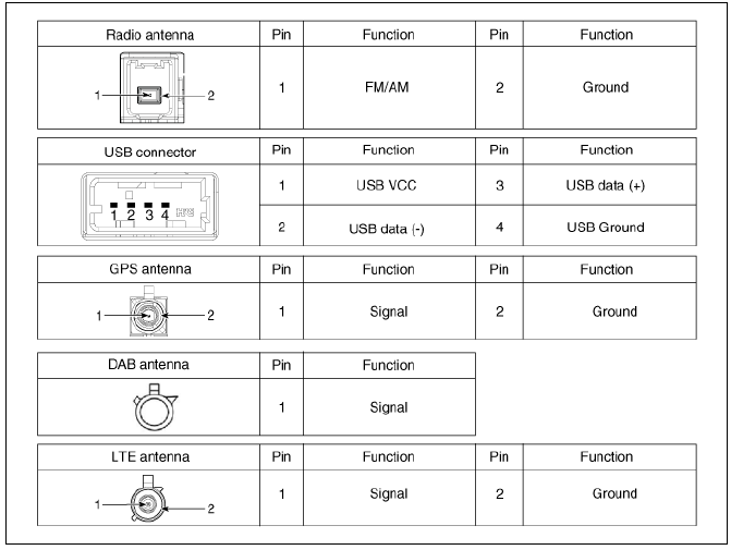
Removal
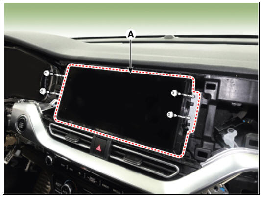
- Remove the crash pad plate (RH) (A).
- Remove the audio/AVN head unit (A) after loosening the mounting screws.
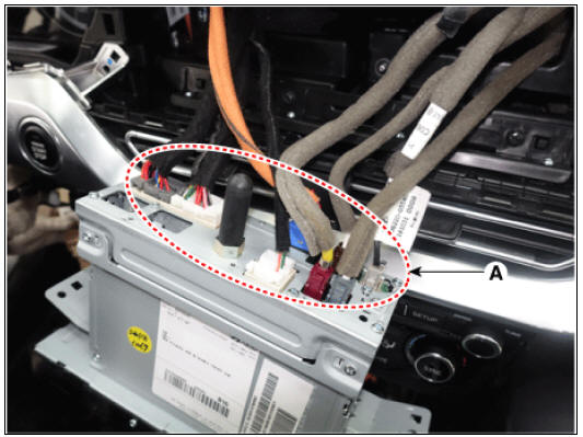
- Disconnect the connectors (A) from the audio/AVN head unit.
Installation
- Install in the reverse order of removal.
Connector and Terminal Function
READ NEXT:
 Vehicle Information Systems (UVO)
AVN head unit
Crash pad LTE antenna (Wi-Fi, LTE 2)
UVO Keypad
Roof LTE antenna (AM/FM + DMB + GPS + LTE 1)
Description
Vehicle information systems (UVO) based on state-of-the-art IT systems,
safety and security
Warning
The term &
Speaker Repair procedures
Troubleshooting of the speakers
Warning
When handling the speakers :
Do not cause shock to the speakers by dropping or throwing
them.
Be careful not to drop water and oil on the speakers.
Use caution to handle the speaker because diaphra
External AMP | Roof Antenna | AVN Remote Controller
Connector Pin Information
External AMP Repair procedures
Removal
Remove the main crash pad.
(Refer to Body - "Main Crash Pad Assembly")
Remove the external amplifier (A) after loosening the mounting bolts and
SEE MORE:
Wheel alignment and tire
balance
The wheels on your vehicle were aligned
and balanced carefully at the factory to
give you the longest tire life and best
overall performance.
If you notice your vehicle vibrating when
driving on a smooth road, your wheels
may need to be rebal
Floor Carpet
Floor Carpet / Repair Procedures
Replacement
Warning
Put on gloves to protect your hands.
Warning
Use a plastic panel removal tool to remove interior trim pieces
without marring the surface.
Be careful not to bend or scratch the tr
Categories
- Home
- KIA Niro EV, Hybrid - Second generation - (SG2) (2021-2024) - Owner's manual
- Kia Niro - First generation - (DE) (2017-2022) - Service and Repair Manual
- Contact Us