KIA Niro: DCT(Dual Clutch Transmission) Repair procedures
Components
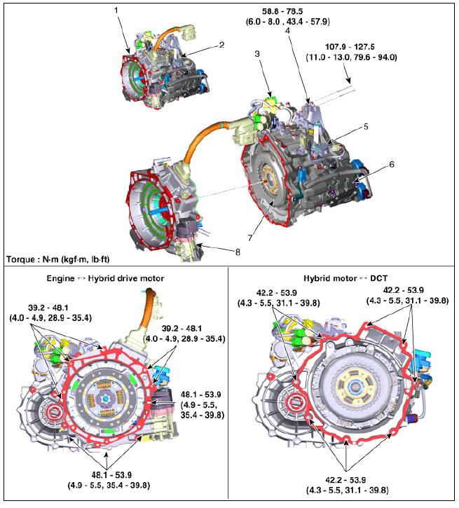
- Hybrid drive motor assembly
- DCT (Double Clutch Transmission) assembly
- Gear actuator assembly
- DCT support bracket
- Inhibitor switch
- Clutch actuator assembly
- Dual clutch assembly
- Engine clutch actuator assembly
Removal
Warning
- Be sure to read and follow the "General Safety Information and Caution" before doing any work related with the high voltage system. Failure to follow the safety instructions may result in serious electrical injuries.
- Be sure to shut off the high voltage circuit according to the "High Voltage Shut-off Procedures" before doing any work related with the high voltage system to avoid serious electrical injuries.
- Shut off the high voltage circuit.
(Refer to Double Clutch Transmission System - "High Voltage Shut-off Procedure")
- Drain the coolant of hybrid cooling system.
(Refer to Hybrid Motor System - "Coolant")
- Remove the hybrid power control unit (HPCU) assembly.
(Refer to Hybrid Control System - "Hybrid Power Control Unit")
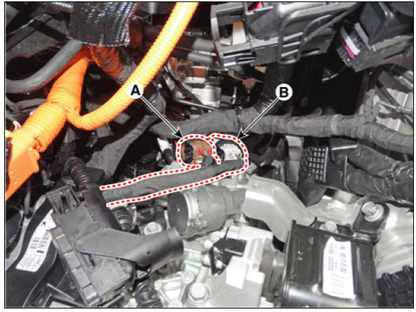
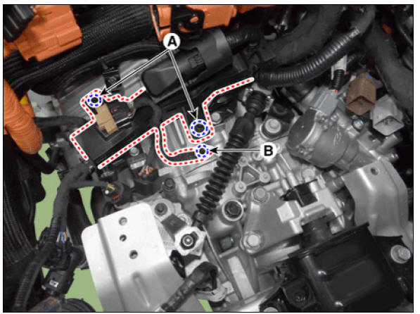
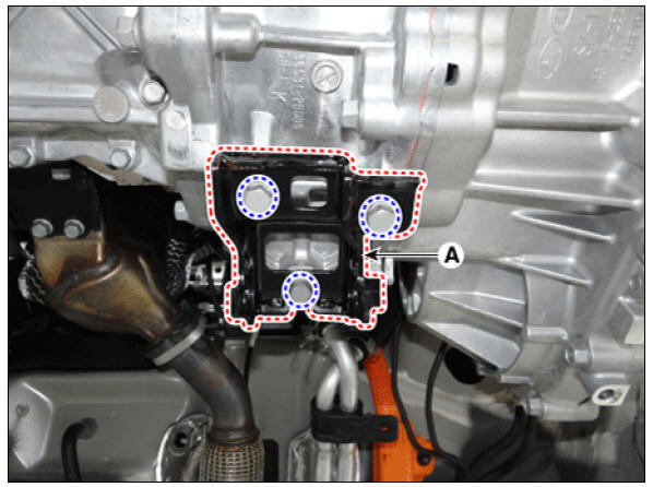
- Disconnect the TCM connector (A) and ECM connector (B).
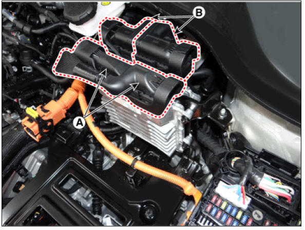
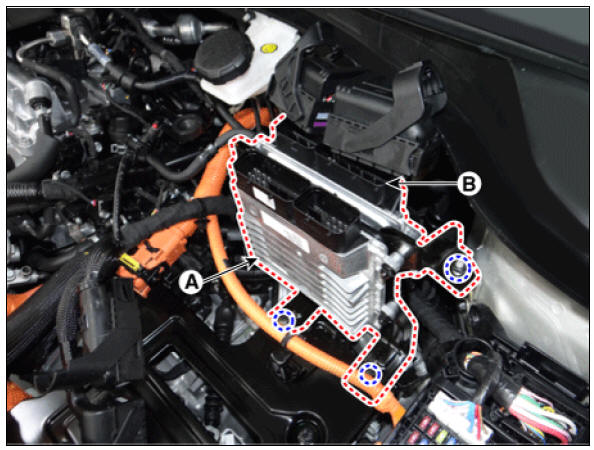
- Remove the TCM (A) and ECM (B).
Tightening torque : 9.8 - 11.8 N*m (1.0 - 1.2 kgf*m, 7.2 - 8.7 lb*ft)
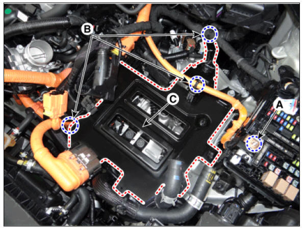
- Remove the HPCU tray (C) after removing the nut (A) and wiring mounting clips (B).
Tightening torque : (A) 10.8 - 13.7 N*m (1.1 - 1.4 kgf*m, 8.0 - 10.1 lb*ft)Disconnect the gear actuator motor connector (A) and gear actuator solenoid connector (B).
(C) 21.6 - 23.5 N*m (2.2 - 2.4 kgf*m, 15.9 - 17.4 lb*ft)
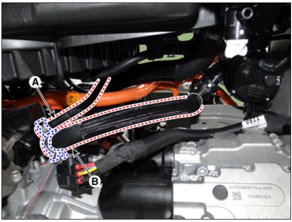
- Disconnect the gear actuator motor connector (A) and gear actuator solenoid connector (B).
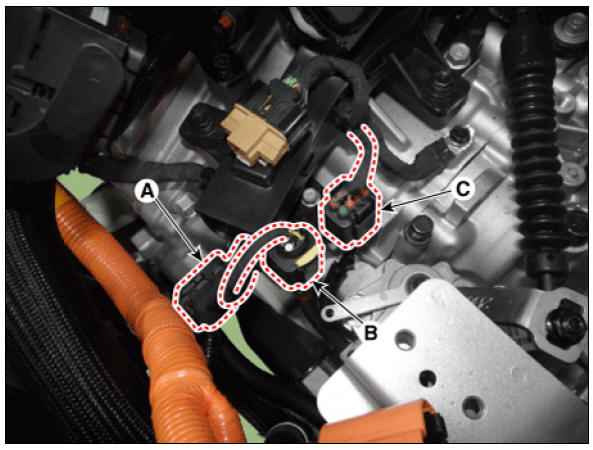
- Disconnect the connectors (A, B, C).
- Clutch actuator connector
- Input speed sensor connector
- Inhibitor switch connector
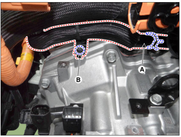
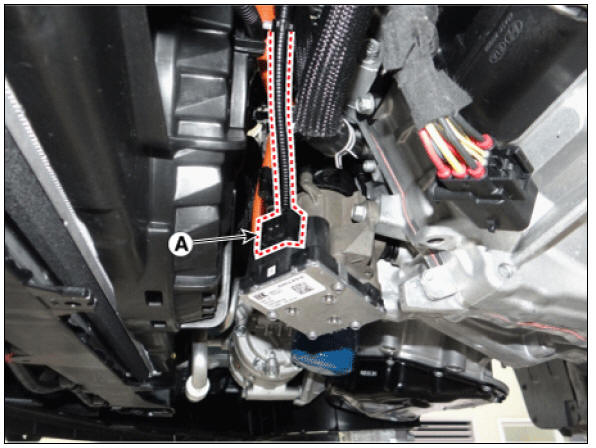
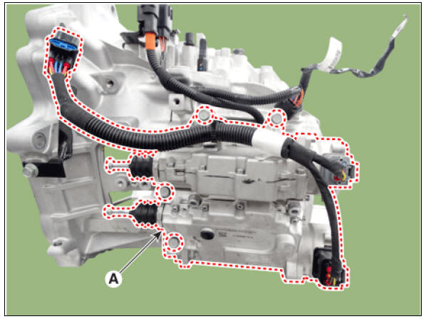
- Disconnect the hybrid drive motor connector (A) and loosen the wiring bracket mounting bolt (B).
Tightening torque : 9.8 - 11.8 N*m (1.0 - 1.2 kgf*m, 7.2 - 8.7 lb*ft)
- Remove the ground (A).
- Loosen the wiring bracket mounting bolt (A) and TCM ground mounting bolt (B).
Tightening torque : 9.8 - 11.8 N*m (1.0 - 1.2 kgf*m, 7.2 - 8.7 lb*ft)
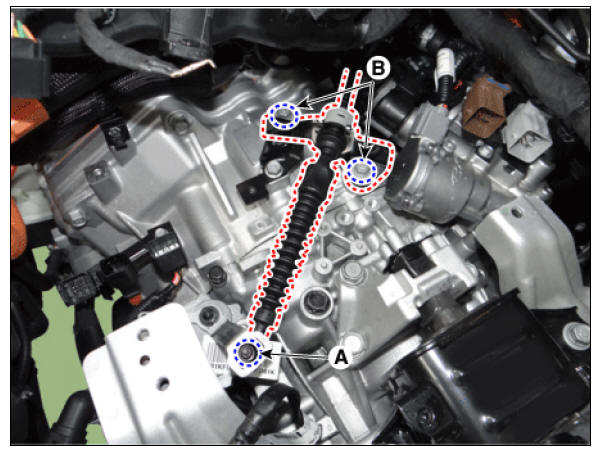
- Remove the shift cable after loosening the bolts (B) and nut (A).
Tightening torque : (A) 9.8 - 14.7 N*m (1.0 - 1.5 kgf*m, 7.2 - 10.8 lb*ft) (B) 19.6 - 26.5 N*m (2.0 - 2.7 kgf*m, 14.5 - 19.5 lb*ft)
- Separate the hybrid motor cooler upper hose and remove the bracket (B).
Tightening torque : 9.8 - 11.8 N*m (1.0 - 1.2 kgf*m, 7.2 - 8.7 lb*ft) 14.
- Loosen the hybrid drive motor upper mounting bolts (A).
Tightening torque : 39.2 - 48.1 N*m (4.0 - 4.9 kgf*m, 28.9 - 35.4 lb*ft)
- Remove the cowl top cover.
(Refer to Body - "Cowl Top Cover")
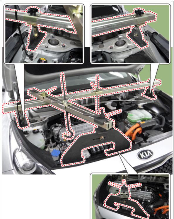
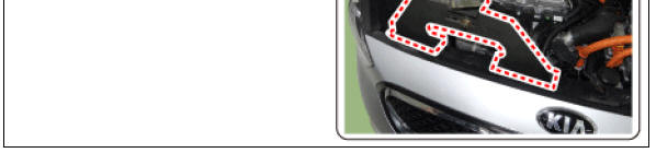
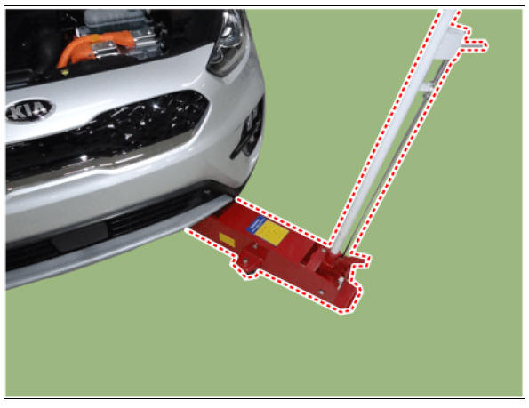
- Assemble the engine support fixture on the engine room.
(Refer to Special Service Tools - "Engine support fixture assembly drawing")
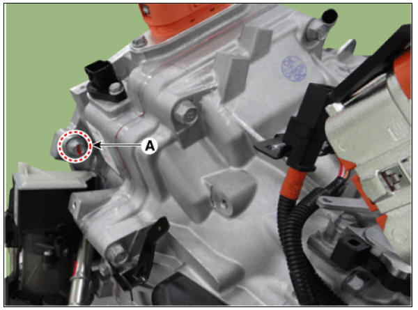
- Remove the cover (A).
- Support the transmission on a jack.
- Remove the transmission mounting bracket bolts (A).
Tightening torque : 88.3 - 107.9 N*m (9.0 - 11.0 kgf*m, 65.1 - 79.6 lb*ft)
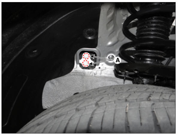
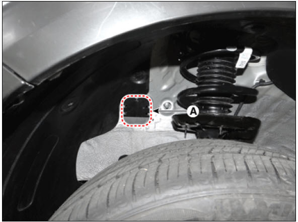
- Remove the transmission support bracket (A).
Tightening torque : 58.9 - 78.5 N*m (6.0 - 8.0 kgf*m, 43.4 - 57.9 lb*ft)
- Remove the sub frame.
(Refer to Suspension System - "Sub Frame")
- Remove the drive shaft assembly.
(Refer to Driveshaft and Axle - "Front Driveshaft")
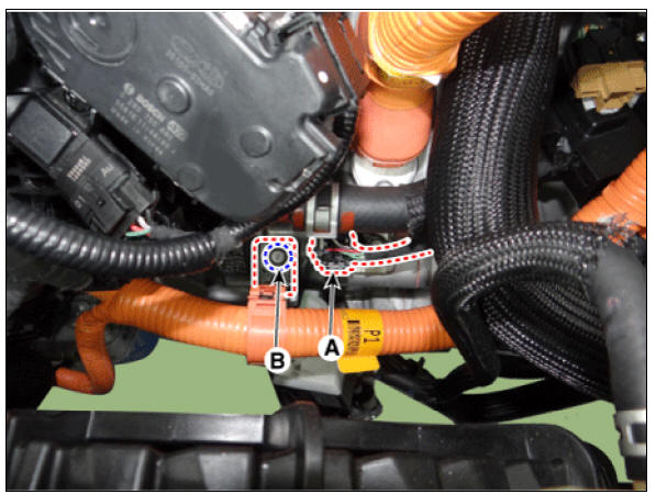
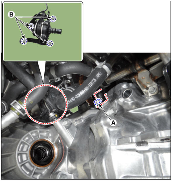
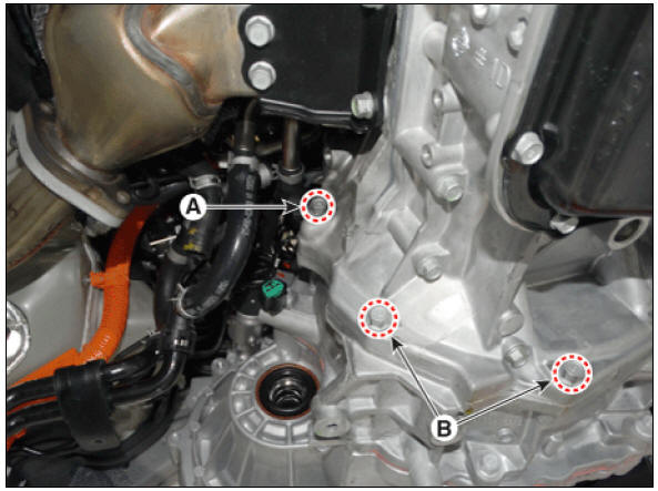
- Remove the CKP sensor loosening a bolt (A) and then loosen the heater pump bracket bolts (B).
Tightening torque :
(A) 7.8 - 11.8 N*m (0.8 - 1.2 kgf*m, 5.8 - 8.7 lb*ft)
(B) 17.7 - 21.6 N*m (1.8 - 2.2 kgf*m, 13.0 - 15.9 lb*ft)
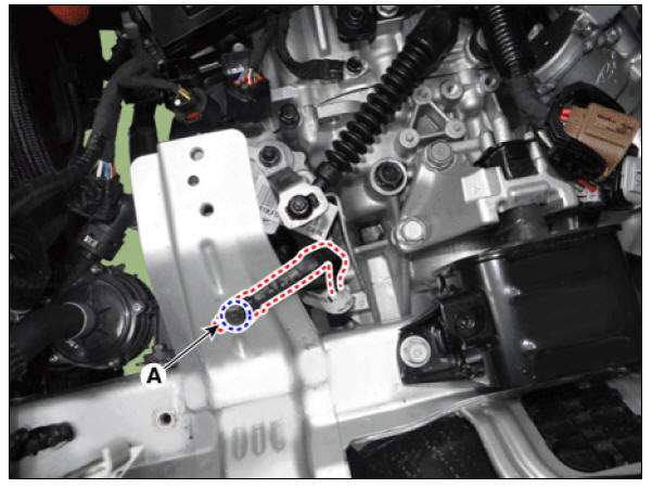
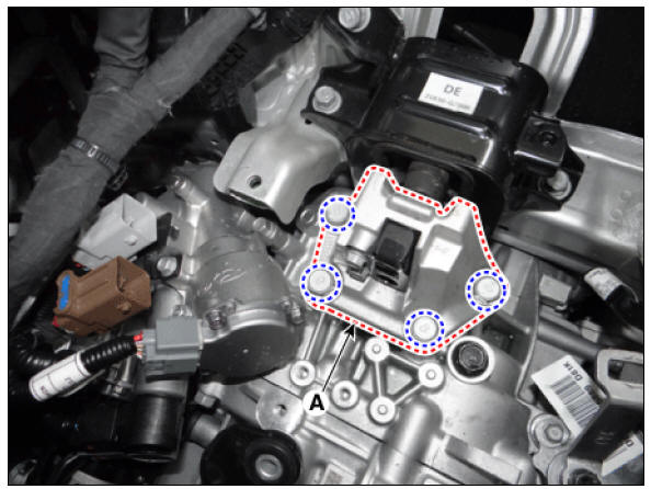
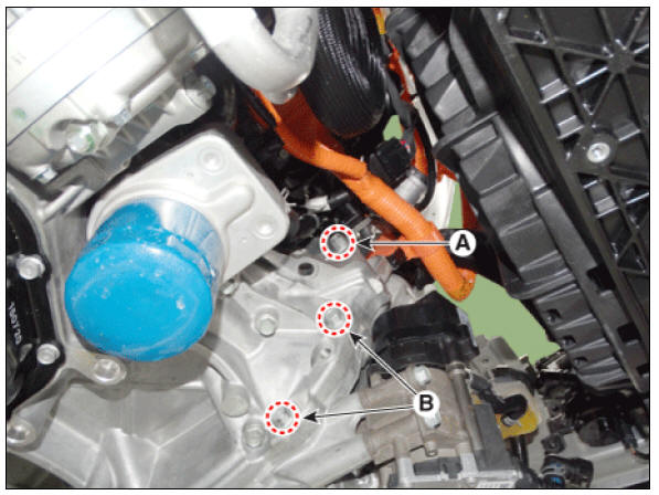
- Remove the roll rod support bracket (A).
Tightening torque : 49.0 - 68.6 N*m (5.0 - 7.0 kgf*m, 36.2 - 50.6 lb*ft
- Disconnect the engine clutch actuator connector (A).
- Saparate engine clutch actuator hose (A) and motor cooler lower hose (B).
Warning
- Do not spill brake fluid on the vehicle or body.
- Cover the hose end to prevent leakage of brake fluid.
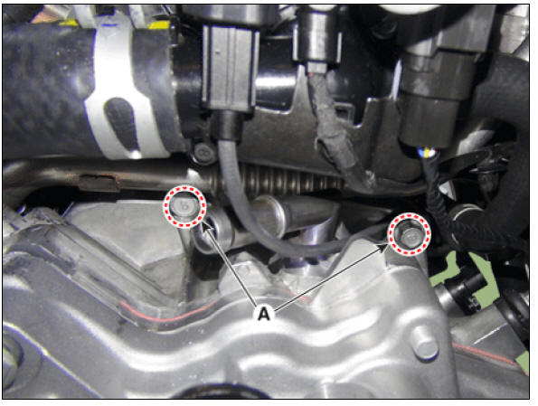
- Loosen the transmission lower mounting bolts (A, B) after supporting the transmission safely on a jack
Tightening torque :
(A) 39.2 - 48.1 N*m (4.0 - 4.9 kgf*m, 28.9 - 35.4 lb*ft)
(B) 48.1 - 53.9 N*m (4.9 - 5.5 kgf*m, 35.4 - 39.8 lb*ft)
- After separating the transmission from the engine, remove the transmission by lowering the jack slowly.
Warning
Be careful not to damage other nearby systems or parts when removing the transmission assembly.
- Remove the hybrid drive motor assembly from the DCT assembly.
(Refer to Hybrid Motor System - "Hybrid Drive Motor Assembly")
Installation
- Install in the reverse order of removal.
Warning
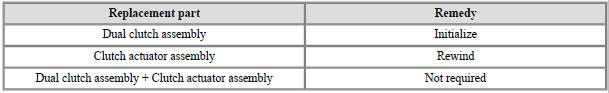
If dual clutch assembly or clutch actuator assembly needs
replacement, perform the work procedures for clutch wear reset by
referring to the table below.
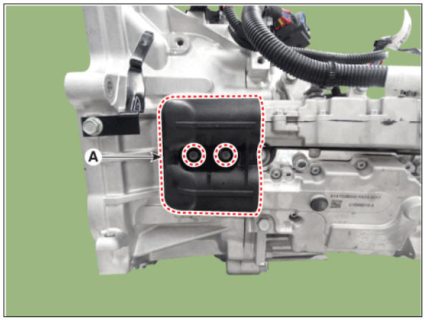
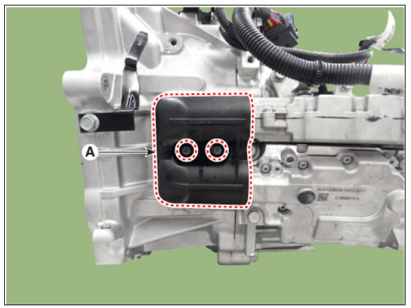
1) Remove the fork cover (A).
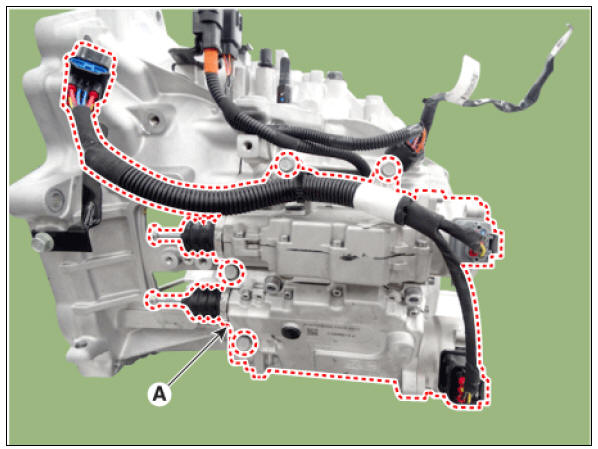
2) Remove the clutch actuator assembly (A).
3) Perform the clutch wear compensation reset.
(Refer to Double Clutch Transmission Control System - "Clutch Actuator
Assembly")
4) Install the the clutch actuator assembly (A).
Tightening torque :
19.6 - 26.5 N*m (2.0 - 2.7 kgf*m, 14.5 - 19.5 lb*ft)
5) Install the fork cover (A).
Tightening torque :
3.9 - 5.9 N*m (0.4 - 0.6 kgf*m, 2.9 - 4.3 lb*ft)
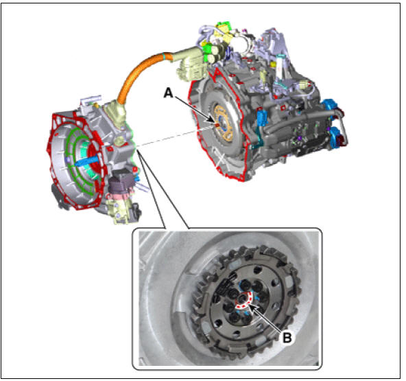
Matters that require attention when installing the dual clutch transmission assembly
1) Check the pilot bearing (B) and motor side connector (A) on the
side of engine for any dents, damages and deformations
before installing the DCT.

2) Align the motor side connector spline (A) with the dual clutch
spline (B).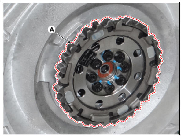
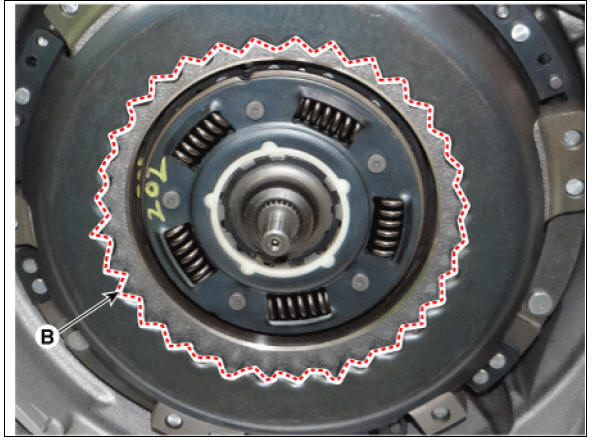
3) Insert the input shaft (A) into the pilot bearing (B) and then
assemble the DCT to the bushing on the motor side.
4) After mounting the DCT to the engine by pushing the DCT, tighten the mounting bolts making sure that there is no gap (less than 2 mm) between the clutch housing and the engine block.
(If the bolt is tightened while there is a gap, then the spline of motor side connector or clutch will be damaged or broken.)
- Observe each separate procedure below for reinstallation or replacement with a new dual clutch transmission.
Warning
When reinstalling
1) If the differential oil seal is damaged and oil is leaking, replace the oil seal with a new one. When installing a new oil seal, use the special tool (09430-C1190, 09231-H1100).
2) Clear the diagnostic trouble codes (DTC) using the KDS. Disconnecting the battery negative terminal will not clear the DTCs.
Clear the DTCs using the KDS at all times.
3) After installing the DCT, check the oil level after refilling the DCT with oil.
(Refer to DCT System - "Transmission Gear Oil") 4) Refill the hybrid motor cooling system with coolant and then perform the air bleeding using the KDS.
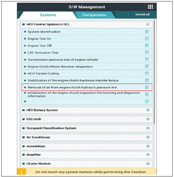
(Refer to Hybrid Motor System - "Coolant") 5) Refill the engine clutch reservoir with brake fluid and then perform the air bleeding using the KDS.

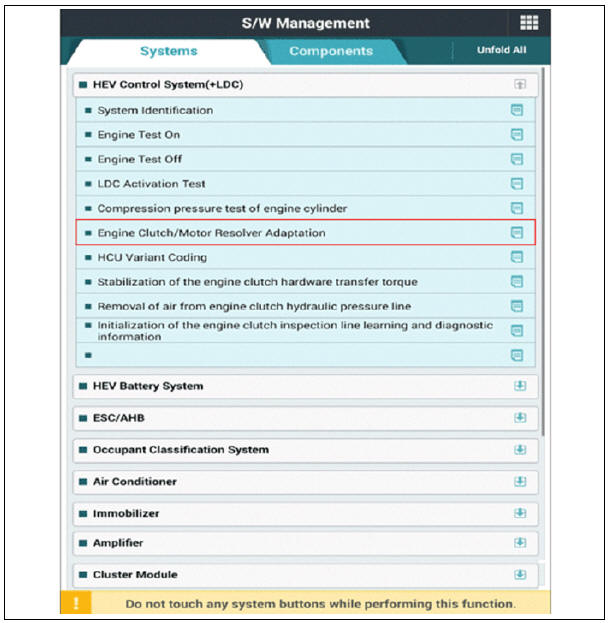
6) Perform the engine clutch / motor resolver adaptation using the KDS.

When replacing with a new dual clutch transmission
1) After replacing the new DCT, it need not oil refill & level check procedure because oil is already filled with specified capacity inside new DCT.
2) Clear the diagnostic trouble codes (DTC) using the KDS. Disconnecting the battery negative terminal will not clear the DTCs.
Clear the DTCs using the KDS at all times.
3) Refill the hybrid motor cooling system with coolant and then perform the air bleeding using the KDS.
(Refer to Hybrid Motor System - "Coolant")
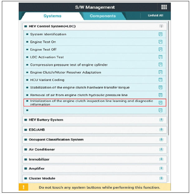
4) Perform initialization of the engine clutch inspection line learning and diagnostic information using the KDS.
5) Refill the engine clutch reservoir with brake fluid and then perform the air bleeding using the KDS.
6) Perform the engine clutch / motor resolver adaptation using the KDS.
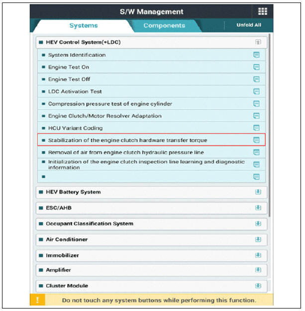
7) Perform of the stabilization of the engine clutch hardware transfer torque using the KDS.
8) Perform clutch characteristics input procedure using the KDS. (One of two procedures must be performed.)
- Clutch characteristics input (Manual Teaching)
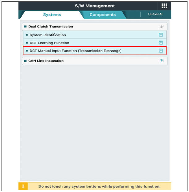
- Clutch touch point learning

READ NEXT:
 Transmission Gear Oil Repair procedures
Oil Level Check
Inspection
Remove the under cover.
(Refer to Engine Mechanical System - "Engine Room Under Cover")
Remove the oil filler plug (A or B).
Check the condition of the oil and make sure that it is at the proper
DCT Control Module (TCM), Repair procedures
Conponent Location
DCT Control Module (TCM)
TCM Connector
TCM Terminal Function
Connector (A)
Connector (B)
Circuit Diagram
Inspection
TCM ground circuit test : Measure the resistance between TCM and chassis grou
SEE MORE:
Sunroof / Repair Procedures
Adjustment
Inspect Glass Alignment
Inspect the step height between the roof panel (A) and the glass
weatherstrip (B) and then adjust it if
necessary.
Alignment adjustment
Standard value (mm(in.))
(1) Front edge : 0 mm (0 in.)
(2) Rear
Ignition System
Description
Ignition timing is controlled by the electronic control ignition timing
system. The standard reference
ignition timing data for the engine operating conditions are preprogrammed in
the memory of the ECM
(Engine Control Module).
Categories
- Home
- KIA Niro EV, Hybrid - Second generation - (SG2) (2021-2024) - Owner's manual
- Kia Niro - First generation - (DE) (2017-2022) - Service and Repair Manual
- Contact Us