KIA Niro: Engine Mounting Repair Procedures
Engine Mounting Components and components location
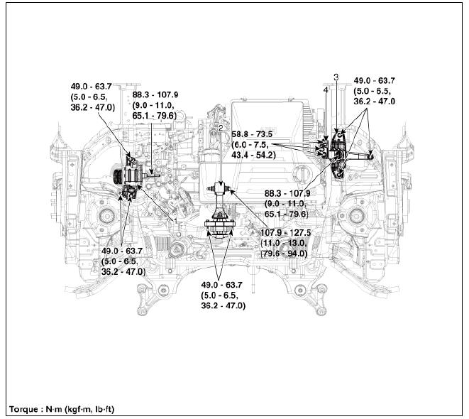
- Transaxle mounting bracket
- Roll rod bracket
- Engine mounting bracket
- Engine mounting support bracket
Engine Mounting Repair Procedures
Removal and
Installation
Engine Mounting Bracket
- Remove the engine room under cover.
(Refer to Engine and Transaxle Assembly - "Engine Room Under Cover")
- Install the jack to the edge of upper oil pan to support the engine.
Warning
Put a rubber block between the jack and oil pan to avoid damaging the oil pan.
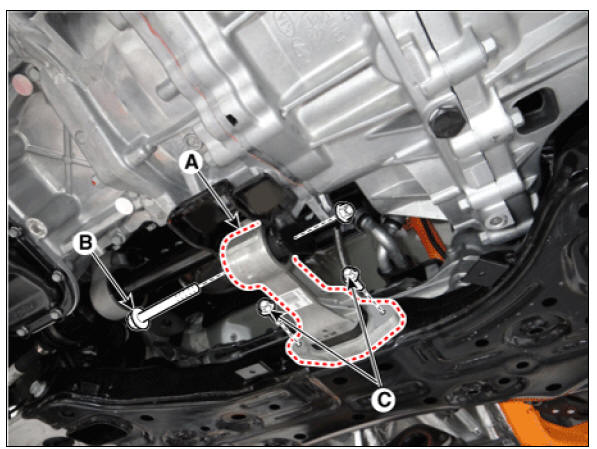
- Remove the engine mounting support bracket (A).
Tightening torque
Nut (B) :
88.3 - 107.9 N*m (9.0 - 11.0 kgf*m, 65.1 - 79.6 lb*ft)
Bolt (C) and nuts (D) :
58.8 - 73.5 N*m (6.0 - 7.5 kgf*m, 43.3 - 54.2 lb*ft)
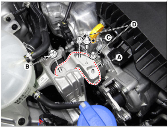
Warning
Do not reuse the bolt C, which is special bolt coated with bond.
- Remove the reservoir tank.
(Refer to Cooling System - "Reservoir Tank")
- Remove the engine mounting bracket (A).
Tightening torque : 49.0 - 63.7 N*m (5.0 - 6.5 kgf*m, 36.2 - 47.0 lb*ft)
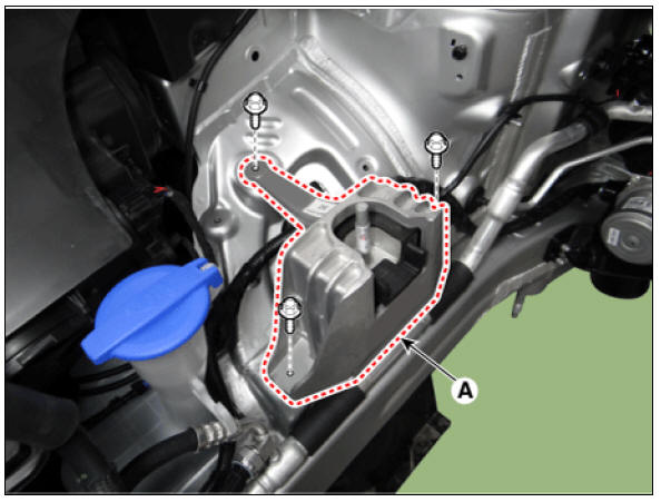
- Install in the reverse order of removal.
Roll Rod Bracket
- Remove the engine room under cover.
(Refer to Engine and Transaxle Assembly - "Engine Room Under Cover")
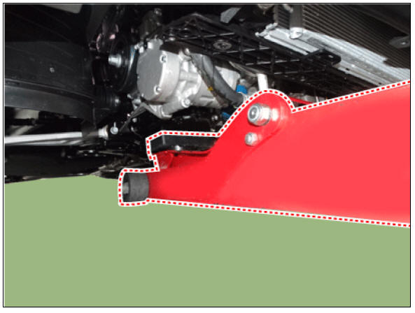
- Remove the roll rod bracket (A).
Tightening torque :
Bolt (B) :
107.9 - 127.5 N*m (11.0 - 13.0 kgf*m, 79.6 - 94.0 lb*ft)
Bolts (C) :
49.0 - 63.7 N*m (5.0 - 6.5 kgf*m, 36.2 - 47.0 lb*ft)
- Install in the reverse order of removal.
Transaxle Mounting Bracket
Warning
- Be sure to read and follow the "General Safety Information and Caution" before doing any work related with the high voltage system. Failure to follow the safety instructions may result in serious electrical injuries.
- Be sure to shut off the high voltage circuit according to the "High Voltage Shut-off Procedures" before doing any work related with the high voltage system to avoid serious electrical injuries.
- Shut off the high voltage circuit.
(Refer to Engine Mechanical System - "High Voltage Shut off Procedure")
- Remove the engine room under cover.
(Refer to Engine and Transaxle Assembly - "Engine Room Under Cover")
- Drain the inverter coolant.
(Refer to Hybrid Motor System - "Coolant")
- Remove the air cleaner assembly.
(Refer to Intake and Exhaust System - "Air Cleaner")
- Remove the hybrid power control unit (HPCU) and tray.
(Refer to Hybrid Control System - "Hybrid Power Control Unit (HPCU)")
- Remove the Engine Control Module (ECM).
(Refer to Engine Control/Fuel System - "Engine Control Module (ECM)")
- Install the jack to the edge of transaxle.
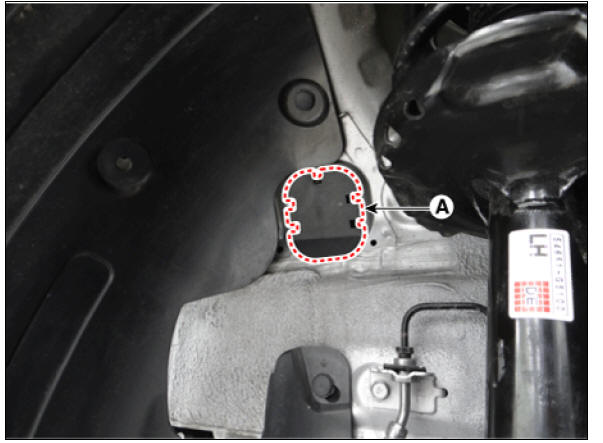
- Remove the transaxle mounting side panel packing (A).
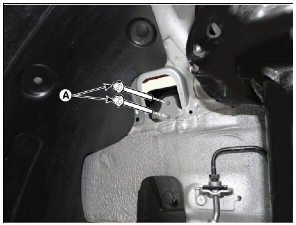
- Remove the transaxle mounting bolt (A).
Tightening torque : 88.3 - 107.9 N*m (9.0 - 11.0 kgf*m, 65.1 - 79.6 lb*ft)
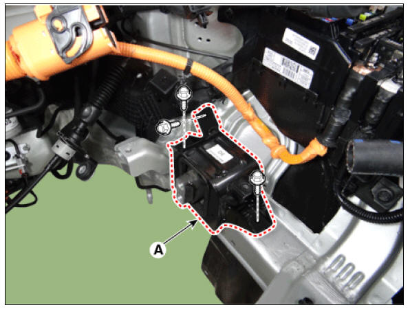
- Remove the transaxle mounting bracket (B).
Tightening torque : 49.0 - 63.7 N*m (5.0 - 6.5 kgf*m, 36.2 - 47.0 lb*ft)
- Install in the reverse order of removal.
READ NEXT:
 Engine And Transaxle Assembly Repair procedures
Removal
Warning
Be sure to read and follow the "General Safety Information and
Caution" before doing any work related with
the high voltage system. Failure to follow the safety instructions may
result in serious electrical injuries.
Be
Air Cleaner Repair procedures
Removal and
Installation
Air Cleaner Assembly
Disconnect the air duct B (A).
Tightening torque :
2.9 - 4.9 N*m (0.3 - 0.5 kgf*m, 2.2 - 3.6 lb*ft)
Disconnect the mass air flow sensor (MAFS) connector (A) and breather
hose (B).
SEE MORE:
Battery (Plug-in hybrid)
For best battery service
* The battery is located in the right side
of the luggage room.
Keep the battery securely mounted.
Keep the battery top clean and dry.
Keep the terminals and connections
clean, tight, and coated with petroleum
Forward Collision-Avoidance Assist settings
Forward safety
A: Driver Assistance
Driving Safety
Forward Safety
With the vehicle on, touch Settings →
Driver Assistance → Driving Safety on
the instrument cluster or Settings →
Vehicle → Driver Assistance → Driving
S
Categories
- Home
- KIA Niro EV, Hybrid - Second generation - (SG2) (2021-2024) - Owner's manual
- Kia Niro - First generation - (DE) (2017-2022) - Service and Repair Manual
- Contact Us