KIA Niro: Exhaust Manifold Repair procedures
Exhaust Manifold Components and components location
Components
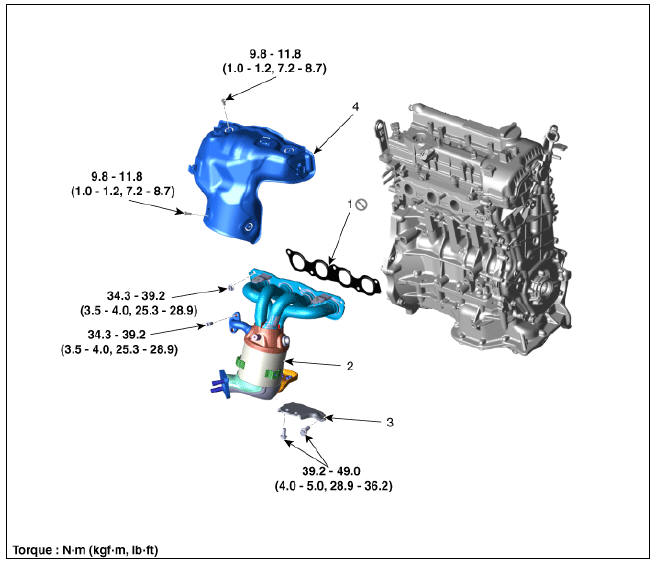
- Exhaust manifold gasket
- Exhaust manifold
- Exhaust manifold stay
- Heat protector
Exhaust Manifold Repair procedures
Removal and Installation
- Remove the engine room under cover.
(Refer to Engine and Transaxle Assembly - "Engine Room Under Cover")
- Remove the air cleaner.
(Refer to Intake and Exhaust System - "Air Cleaner")
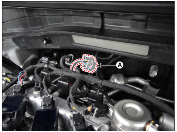
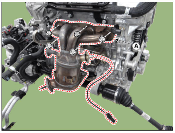
- Disconnect the front oxygen sensor (A).
- Remove the front muffler.
(Refer to Intake and Exhaust System - "Muffler")
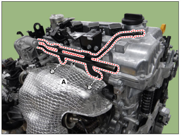
- Separate the water return & degas pipe (A).
Tightening torque : 18.6 - 23.5 N*m (1.9 - 2.4 kgf*m, 13.7 - 17.4 lb*ft)
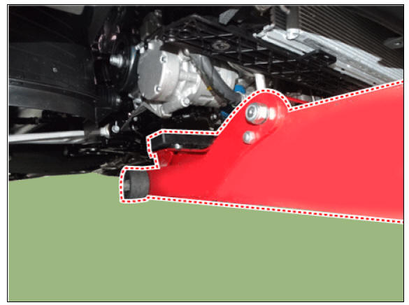
- Remove the exhaust manifold stay (A).
Tightening torque : 39.2 - 49.0 N*m (4.0 - 5.0 kgf*m, 28.9 - 36.2 lb*ft)
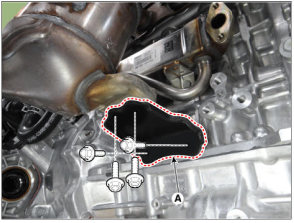
- Remove the engine mounting support bracket.
(1) Install the jack to the edge of the lower oil pan to support the engine.
Warning
Insert the rubber block between jack and upper oil pan.
(2) Remove the engine mounting support bracket (A).
Tightening torque
Nut (B) :
88.3 - 107.9 N*m (9.0 - 11.0 kgf*m, 65.1 - 79.6 lb*ft)
Bolt (C) and nuts (D) :
58.8 - 73.5 N*m (6.0 - 7.5 kgf*m, 43.3 - 54.2 lb*ft)
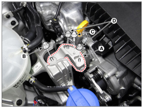
Warning
Do not reuse the bolt C, which is special bolt coated with bond.
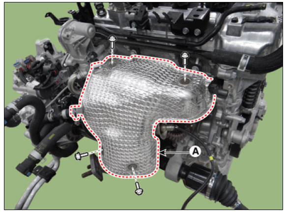
- Remove the heat protector (A).
Tightening torque : 9.8 - 11.8 N*m (1.0 - 1.2 kgf*m, 7.2 - 8.7 lb*ft)
- Remove the EGR cooler pipe A (A).
Tightening torque : 34.3 - 39.2 N*m (3.5 - 4.0 kgf*m, 25.3 - 28.9 lb*ft)
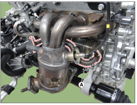
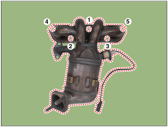
- Remove the exhaust manifold (A).
Tightening torque : 34.3 - 39.2 N*m (3.5 - 4.0 kgf*m, 25.3 - 28.9 lb*ft)
Warning
When installing the exhaust manifold, tighten the nuts to pre-torque
first and then fully tighten to the
specified torque in the sequence shown.
- Remove the exhaust manifold gasket (A).
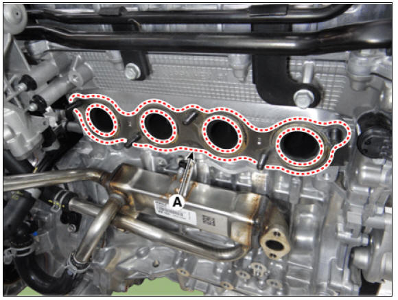
Warning
When installing, replace with a new gasket.
- Install in the reverse order of removal.
READ NEXT:
 Muffler Repair procedures
Muffler Components and components location
Components
Front muffler
GPF
Center muffler
Rear muffler
Gasket
Rubber hanger
Muffler Repair procedures
Removal and
Installation
Front Muffler
Disconnect the heated oxygen sensor
Engine Oil Repair procedures
Warning
Prolonged and repeated contact with mineral oil will result in
the removal of natural fats from the skin, leading to
dryness, irritation and dermatitis. In addition, used engine oil contains
potentially harmful contaminants which
SEE MORE:
Vehicle settings (infotainment system)
Press the Settings button on the head
unit of the infotainment system.
Select Vehicle and change the setting
of the features.
Vehicle Settings in the infotainment system
provides user options for a variety
of settings including door
TJ Joint Repair procedures
Removal
Warning
Drive shaft joints require special grease, so do not add any
other type of grease.
When replacing the boot band, it must be a new one.
Remove the front drive shaft.
(Refer to Driveshaft Assembly - "Front Drive
Categories
- Home
- KIA Niro EV, Hybrid - Second generation - (SG2) (2021-2024) - Owner's manual
- Kia Niro - First generation - (DE) (2017-2022) - Service and Repair Manual
- Contact Us