KIA Niro: Fly Wheel Repair procedures
Kia Niro - First generation - (DE) (2017-2022) - Service and Repair Manual / Engine Mechanical System / Cylinder Block / Fly Wheel Repair procedures
Components
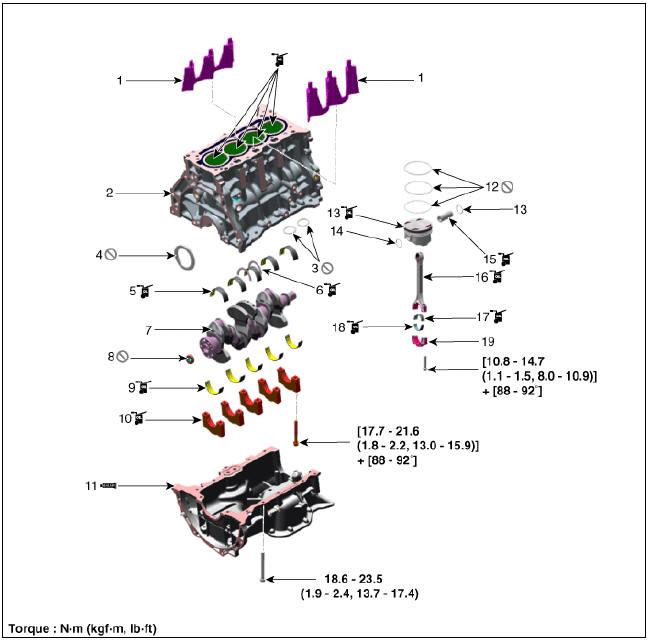
- Water jacket insert
- Cylinder block
- Oil ring
- Rear oil seal
- Crankshaft upper bearing
- Thrust bearing
- Crankshaft
- Pilot bearing
- Crankshaft lower bearing
- Crankshaft lower bearing cap
- Ladder frame
- Piston ring
- Piston
- Snap ring
- Piston pin
- Connecting rod
- Connecting rod upper bearing
- Connecting rod lower bearing
- Connecting rod bearing cap
Fly Wheel Repair procedures
Removal and Installation
Warning
- Be sure to read and follow the "General Safety Information and Caution" before doing any work related with the high voltage system. Failure to follow the safety instructions may result in serious electrical injuries.
- Be sure to shut off the high voltage circuit according to the "High Voltage Shut-off Procedures" before doing any work related with the high voltage system to avoid serious electrical injuries
- Shut off the high voltage circuit.
(Refer to Engine Mechanical System - "High Voltage Shut off Procedure")
- Remove the dual clutch transmission.
(Refer to Double Clutch Transmission (DCT) - "Double Clutch Transmission Assembly")
- Remove the engine clutch disk and clutch cover.
(Refer to Engine Clutch System - "Clutch Cover and Disk")
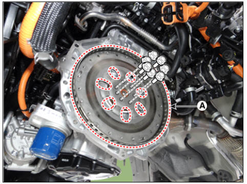
- Remove the flywheel (A).
Tightening torque : 78.5 - 88.3 N*m (8.0 - 9.0 kgf*m, 57.9 - 65.1 lb*ft)
Warning
Always use new flywheel bolts.
- Install in the reverse order of removal.
Water Jacket Insert Repair procedures
Removal and
Installation
- Remove the cylinder head.
(Refer to Cylinder Head Assembly - "Cylinder Head")
- Remove the water jacket insert (A).
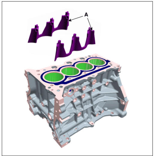
- Install in the reverse order of removal.
READ NEXT:
 Rear Oil Seal Repair procedures
Replacement
Warning
Be sure to read and follow the "General Safety Information and
Caution" before doing any
work related with the high voltage system. Failure to follow the safety
instructions may result in
serious electrical injuries
Piston and Connecting Rod Repair procedures
Disassembly
Warning
Be sure to read and follow the "General Safety Information and
Caution" before doing any work related
with the high voltage system. Failure to follow the safety instructions may
result in serious electrical
injuries
Connecting Rod
Check the connecting rod side clearance.
Using a feeler gauge, measure the end play while moving the connecting rod
back and forth.
If out-of-tolerance, install a new connecting rod.
If still out-of-tolerance, replace the crankshaft.
SEE MORE:
AHB(Active Hydraulic Boost) System / Description And Operation
Regeneration Brake System
During deceleration or braking of an electric vehicle or HEV, the drive motor
acts as an alternator and charges the battery by
converting the vehicle's kinetic energy generated during braking into electrical
energy. Re
Crash Pad Lower Panel | Glove Box Housing
Crash pad lower panel
Crash Pad Lower Panel Repair procedures
Replacement
Warning
Put on gloves to protect your hands.
Warning
Use a plastic panel removal tool to remove interior trim pieces without marring the surface.
B
Categories
- Home
- KIA Niro EV, Hybrid - Second generation - (SG2) (2021-2024) - Owner's manual
- Kia Niro - First generation - (DE) (2017-2022) - Service and Repair Manual
- Contact Us