KIA Niro: Front Lower Arm Repair procedures
Kia Niro - First generation - (DE) (2017-2022) - Service and Repair Manual / Suspension System / Front Suspension System / Front Lower Arm Repair procedures
Front Lower Arm Components and components location
Components
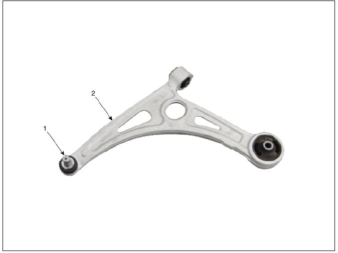
- Ball joint assembly
- Front lower arm assembly
Front Lower Arm Repair procedures
Removal
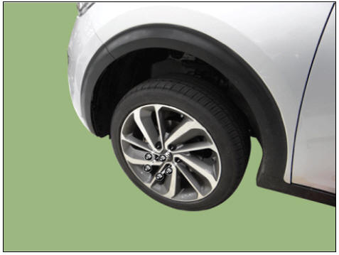
- Remove the wheel and tire.
Tightening torque: 107.9 - 127.5 N*m (11.0 - 13.0 kgf*m, 79.6 - 94.0 lb*ft)
Warning
Be careful not to damage the wheel nuts when removing the wheel and tire.
- Remove the under cover.
(Refer to Engine Mechanical System - "Engine Room Under Cover")
- Disconnect the lower arm from the knuckle by using the SST
(09568-1S100).
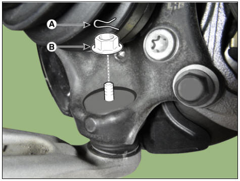
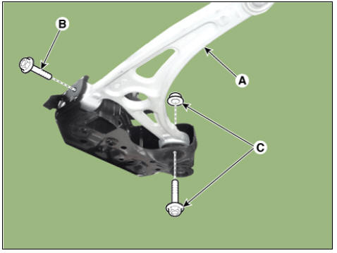
(1) Remove the lower arm pin (A) and nut (B).
Tightening torque : 78.5 - 98.1 N*m (8.0 - 10.0 kgf*m, 57.9 - 72.3 lb*ft)
(2) Disconnect the lower arm from the knuckle by using the SST (09568-1S100).
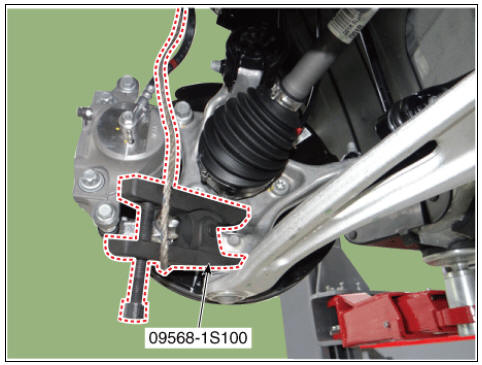
Warning
- When using SST, be sure not to damage the dust cover of lower arm ball joint.
- Keep SST tied to the car because there is a risk of injury by dropping the SST during removing the lower arm ball joint.
- The peripheral parts may be damaged when removing the lower arm ball joint with a general tool such as lever, so be sure to use SST.
- Remove the lower arm (A) from the sub frame.
Tightening torque: B : 117.7 - 137.3 N*m (12.0 - 14.0 kgf*m, 86.8 - 101.3 lb*ft) C : 156.9 - 176.5 N*m (16.0 - 18.0 kgf*m, 115.7 - 130.2 lb*ft)
- Install in the reverse order of removal.
- Check the wheel alignment.
(Refer to Tires/Wheels - "Alignment")
Inspection
- Check the bushing for wear and deterioration.
- Check the lower arm for bending or breakage.
- Check the lower arm for deformation.
- Check all bolts and nuts.
READ NEXT:
 Front Stabilizer Bar
Front Stabilizer Bar Components and components location
Stabilizer bar
Stabilizer link
Front Stabilizer Bar Repair procedures
Removal
Disconnect the battery negative cable.
Remove the universal bolt (A).
Tightening torque :
32
Sub Frame Repair procedures
Removal
Disconnect the battery negative cable.
Remove the universal bolt (A).
Tightening torque :
32.4 - 37.3 N*m (3.3 - 3.8 kgf*m, 23.9 - 27.5 lb*ft)
Warning
Keep neutral range to prevent damaging the clock spring inner
cable w
SEE MORE:
Our recommendation: Children always in the rear
Infants and younger children must be
restrained in an appropriate rearwardfacing
or forward-facing CRS that has
first been properly secured to the seat of
the vehicle. Read and comply with the
instructions for installation and use provided
by t
Tires and wheels
(Kia Niro EV / Hybrid)
*1. Load Index
*2. Speed Symbol
CAUTION
When replacing tires, use the same size
originally supplied with the vehicle.
Using tires of a different size can damage
the related parts or make it work
irregularly.
NOTI
Categories
- Home
- KIA Niro EV, Hybrid - Second generation - (SG2) (2021-2024) - Owner's manual
- Kia Niro - First generation - (DE) (2017-2022) - Service and Repair Manual
- Contact Us