KIA Niro: Front Stabilizer Bar
Front Stabilizer Bar Components and components location
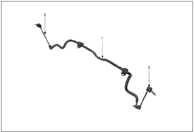
- Stabilizer bar
- Stabilizer link
Front Stabilizer Bar Repair procedures
Removal
- Disconnect the battery negative cable.
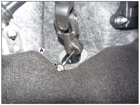
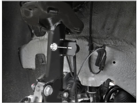
- Remove the universal bolt (A).
Tightening torque : 32.4 - 37.3 N*m (3.3 - 3.8 kgf*m, 23.9 - 27.5 lb*ft)
Warning
- Keep neutral range to prevent damaging the clock spring inner cable when steering the wheel.
- Do not reuse the bolt.
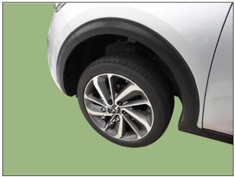
- Remove the wheel and tire.
Tightening torque: 107.9 - 127.5 N*m (11.0 - 13.0 kgf*m, 79.6 - 94.0 lb*ft)
Warning
Be careful not to damage the wheel nuts when removing the wheel and tire.
- Remove the under cover.
(Refer to Engine Mechanical System - "Engine Room Under Cover")
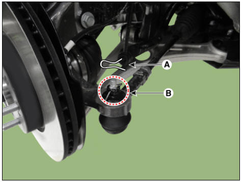
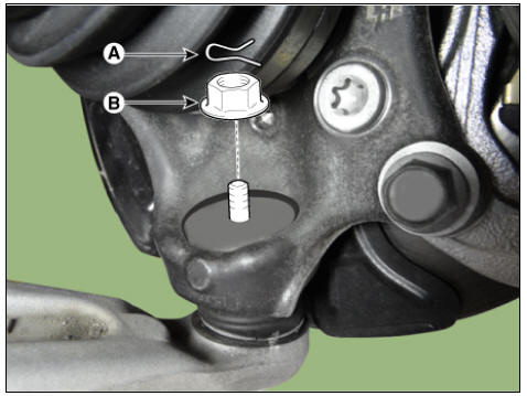
- Remove the tie rod end pin (A) and nub (B).
Tightening torque: 78.4 - 98.0 N*m (8.0 - 10.0 kgf*m, 57.8 - 72.3 lb*ft)
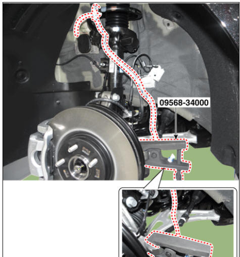
- Remove the knuckle by using the SST (09568-34000).
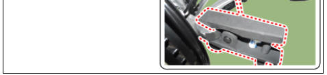
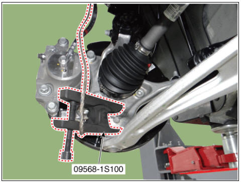
- Disconnect the lower arm from the knuckle by using the SST (09568-1S100).
(1) Remove the lower arm pin (A) and nut (B).
Tightening torque : 78.5 - 98.1 N*m (8.0 - 10.0 kgf*m, 57.9 - 72.3 lb*ft)
(2) Disconnect the lower arm from the knuckle by using the SST (09568-1S100).
Warning
- When using SST, be sure not to damage the dust cover of lower arm ball joint.
- Keep SST tied to the car because there is a risk of injury by dropping the SST during removing the lower arm ball joint.
- The peripheral parts may be damaged when removing the lower arm ball joint with a general tool such as lever, so be sure to use SST.
- Remove the stabilizer link nut.
Tightening torque: 98.0 - 117.6 N*m (10.0 - 12.0 kgf*m, 72.3 - 86.7 lb*ft)
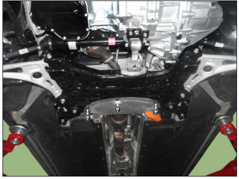
- Loosen the nuts and then remove the heat protector.
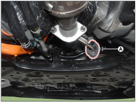
- Remove the hanger (A).
- Remove the roll rod bracket.
(Refer to Engine Mechanical System - "Engine Mounting")
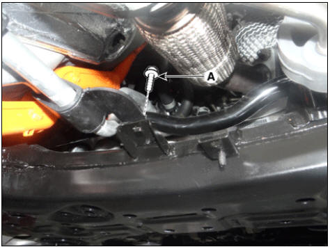
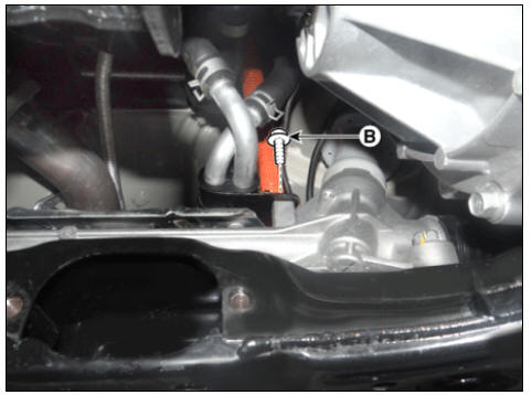
- Loosen the bolts (A) and (B) and then remove the coolant pipe.
Tightening torque: 6.8 - 10.7 N*m (0.7 - 1.1 kgf*m, 5.0 - 7.9 lb*ft)
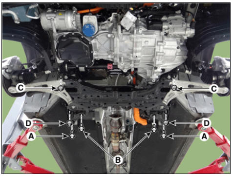
- Loosen the bolts (A,B) and nuts (C,D) and then remove the sub frame (D).
Tightening torque: Bolts : (A) 44.1 - 53.9 N*m (4.5 - 5.5 kgf*m, 32.5 - 39.8 lb*ft) (B) 176.5 - 196.1 N.m (18.0 - 20.0 kgf.m, 130.2 - 144.6 lb-ft) Nuts : (C) 176.5 - 196.1 N.m (18.0 - 20.0 kgf.m, 130.2 - 144.6 lb-ft) (D) 44.1 - 53.9 N*m (4.5 - 5.5 kgf*m, 32.5 - 39.8 lb*ft)
Warning
Set up the transmission jack under the subframe in order to remove the shock absorber in no-load condition .
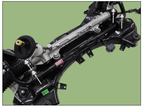
- Loosen the bolts and then remove the gearbox heat protector.
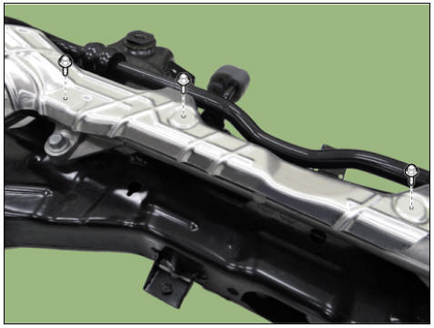
- Loosen the bolts and then remove the front stabilizer bar.
Tightening torque: 44.1 - 53.9 N*m (4.5 - 5.5 kgf*m, 32.5 - 39.8 lb*ft)
- Install in the reverse order of removal.
- Check the wheel alignment.
(Refer to Suspension System - "Alignment")
Inspection
- Check the bushing for wear and deterioration.
- Check the front stabilizer bar for deformation.
- Check the front stabilizer link ball joint for damage.
READ NEXT:
 Sub Frame Repair procedures
Removal
Disconnect the battery negative cable.
Remove the universal bolt (A).
Tightening torque :
32.4 - 37.3 N*m (3.3 - 3.8 kgf*m, 23.9 - 27.5 lb*ft)
Warning
Keep neutral range to prevent damaging the clock spring inner
cable w
Rear Shock Absorber Repair procedures
Rear Suspension System / Components And Components Location
Stabilizer bar
Rear sub frame
Rear upper arm
Rear shock absorber
Rear axle
Assist arm
Trailing arm
Coil spring
Rear Shock Absorber Repair procedures
Removal
Dis
SEE MORE:
Floor Carpet
Floor Carpet / Repair Procedures
Replacement
Warning
Put on gloves to protect your hands.
Warning
Use a plastic panel removal tool to remove interior trim pieces
without marring the surface.
Be careful not to bend or scratch the tr
Nearby stations
A: Electric Vehicle
Select EV and see the map from the
infotainment system screen. Stations
around the current location are
searched.
A: Electric Vehicle
Select the icon on the screen.
Around the course, around the current
site, aro
Categories
- Home
- KIA Niro EV, Hybrid - Second generation - (SG2) (2021-2024) - Owner's manual
- Kia Niro - First generation - (DE) (2017-2022) - Service and Repair Manual
- Contact Us