KIA Niro: Sub Frame Repair procedures
Removal
- Disconnect the battery negative cable.
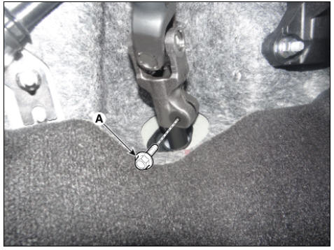
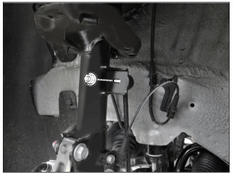
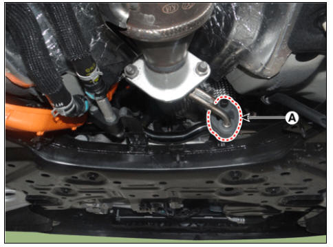
- Remove the universal bolt (A).
Tightening torque : 32.4 - 37.3 N*m (3.3 - 3.8 kgf*m, 23.9 - 27.5 lb*ft)
Warning
- Keep neutral range to prevent damaging the clock spring inner cable when steering the wheel.
- Do not reuse the bolt.
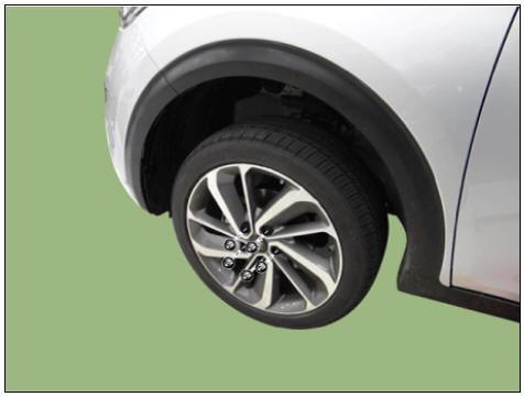
- Remove the wheel and tire.
Tightening torque: 107.9 - 127.5 N*m (11.0 - 13.0 kgf*m, 79.6 - 94.0 lb*ft)
Warning
Be careful not to damage the wheel nuts when removing the wheel and tire.
- Remove the under cover.
(Refer to Engine Mechanical System - "Engine Room Under Cover")
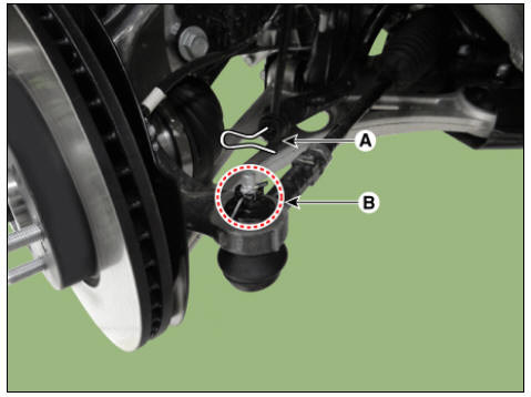
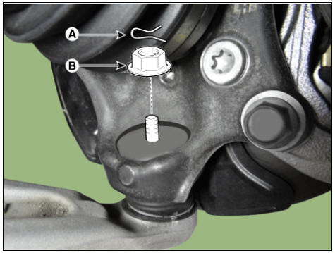
- Remove the tie rod end pin (A) and nub (B).
Tightening torque: 78.4 - 98.0 N*m (8.0 - 10.0 kgf*m, 57.8 - 72.3 lb*ft)
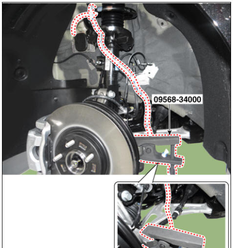
- Remove the knuckle by using the SST (09568-34000).
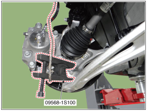
- Disconnect the lower arm from the knuckle by using the SST
(09568-1S100).
(1) Remove the lower arm pin (A) and nut (B).
Tightening torque : 78.5 - 98.1 N*m (8.0 - 10.0 kgf*m, 57.9 - 72.3 lb*ft)
(2) Disconnect the lower arm from the knuckle by using the SST (09568-1S100).
Warning
- When using SST, be sure not to damage the dust cover of lower arm ball joint.
- Keep SST tied to the car because there is a risk of injury by dropping the SST during removing the lower arm ball joint.
- The peripheral parts may be damaged when removing the lower arm ball joint with a general tool such as lever, so be sure to use SST.
- Remove the stabilizer link nut.
Tightening torque: 98.0 - 117.6 N*m (10.0 - 12.0 kgf*m, 72.3 - 86.7 lb*ft)
- Loosen the nuts and then remove the heat protector.

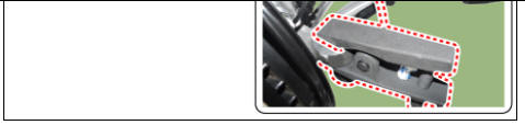
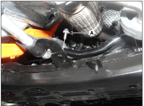
- Remove the hanger (A).
- Remove the roll rod bracket.
(Refer to Engine Mechanical System - "Engine Mounting")
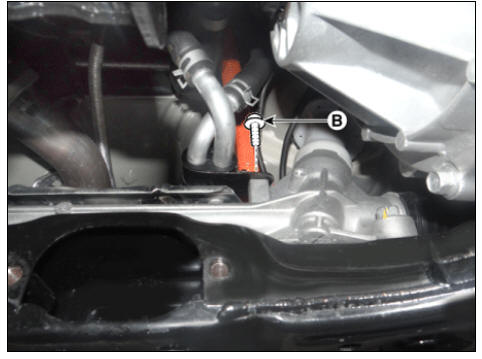
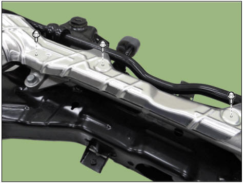
- Loosen the bolts (A) and (B) and then remove the coolant pipe.
Tightening torque: 6.8 - 10.7 N*m (0.7 - 1.1 kgf*m, 5.0 - 7.9 lb*ft)
- Loosen the bolts (A,B) and nuts (C,D) and then remove the sub frame (D).
Tightening torque: Bolts : (A) 44.1 - 53.9 N*m (4.5 - 5.5 kgf*m, 32.5 - 39.8 lb*ft) (B) 176.5 - 196.1 N.m (18.0 - 20.0 kgf.m, 130.2 - 144.6 lb-ft) Nuts : (C) 176.5 - 196.1 N.m (18.0 - 20.0 kgf.m, 130.2 - 144.6 lb-ft) (D) 44.1 - 53.9 N*m (4.5 - 5.5 kgf*m, 32.5 - 39.8 lb*ft)
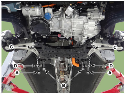
Warning
Set up the transmission jack under the subframe in order to remove the shock absorber in no-load condition .
- Loosen the bolts and then remove the gearbox heat protector.
- Loosen the bolts and then remove the front stabilizer bar.
Tightening torque: 44.1 - 53.9 N*m (4.5 - 5.5 kgf*m, 32.5 - 39.8 lb*ft)
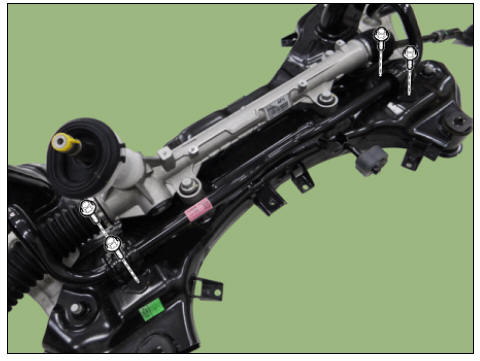
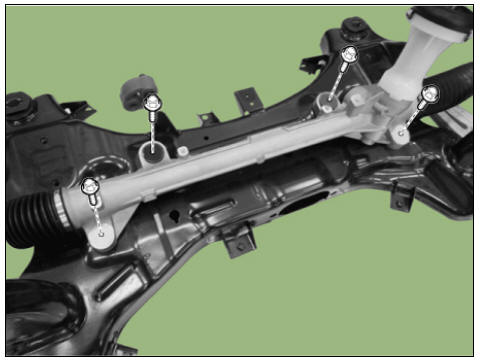
- Loosen the bolts and then remove the gear box.
Tightening torque: 88.3 - 107.9 - 127.5 N*m (9.0 - 11.0 kgf*m, 65.1 - 79.6 lb*ft)
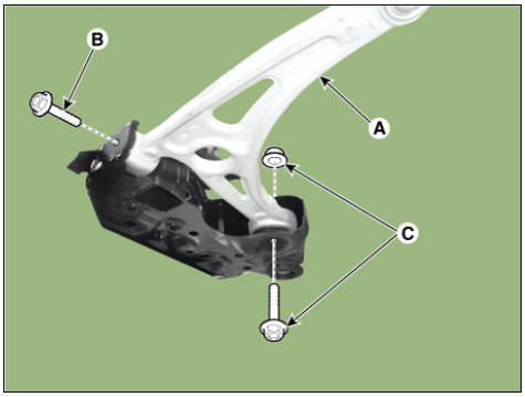
- Loosen the bolts (B,C) and then remove the lower arm (A) from the sub frame.
Tightening torque: (B) 117.7 - 137.3 N*m (12.0 - 14.0 kgf*m, 86.8 - 101.3 lb*ft) (C) 156.9 - 176.5 N*m (16.0 - 18.0 kgf*m, 115.7 - 130.2 lb*ft)
- Install in the reverse order of removal.
- Check the wheel alignment.
(Refer to Suspension System - "Alignment")
READ NEXT:
 Rear Shock Absorber Repair procedures
Rear Suspension System / Components And Components Location
Stabilizer bar
Rear sub frame
Rear upper arm
Rear shock absorber
Rear axle
Assist arm
Trailing arm
Coil spring
Rear Shock Absorber Repair procedures
Removal
Dis
Rear Lower and Upper Arm Repair procedures
Removal
Disconnect the battery negative cable.
Remove the wheel and tire.
Tightening torque: 107.9 - 127.5 N*m (11.0 - 13.0 kgf*m, 79.6 - 94.0 lb*ft)
Warning
Be careful not to damage the wheel nuts when removing the wheel and tire
SEE MORE:
Replacing license plate lamp (Bulb
type)
Operation
Turn off vehicle and disconnect the
negative terminal from the battery.
Using a screwdriver, gently pry the
lamp assembly.
Remove the bulb by pulling it straight
out.
Install a new bulb in the socket.
Install the lamp
Multi-Collision Brake (MCB)
Multi-Collision Brake controls the brake
automatically in the event of an accident
where the air bag deploys to reduce the
risk of additional accidents that may
occur.
System operation
From the time the air bag deploys,
Multi-Collision Brake m
Categories
- Home
- KIA Niro EV, Hybrid - Second generation - (SG2) (2021-2024) - Owner's manual
- Kia Niro - First generation - (DE) (2017-2022) - Service and Repair Manual
- Contact Us