KIA Niro: Rear Shock Absorber Repair procedures
Kia Niro - First generation - (DE) (2017-2022) - Service and Repair Manual / Suspension System / Rear Suspension System / Rear Shock Absorber Repair procedures
Rear Suspension System / Components And Components Location
- Stabilizer bar
- Rear sub frame
- Rear upper arm
- Rear shock absorber
- Rear axle
- Assist arm
- Trailing arm
- Coil spring
Rear Shock Absorber Repair procedures
Removal
- Disconnect the battery negative cable.
- Remove the wheel nuts and tire.
Tightening torque: 107.9 - 127.5 N*m (11.0 - 13.0 kgf*m, 79.6 - 94.0 lb*ft)
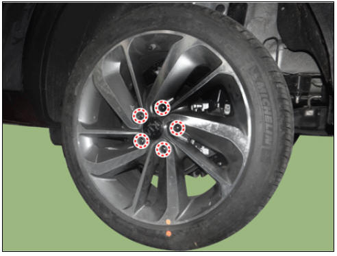
Warning
Be careful not to damage the wheel nuts when removing the wheel and tire.
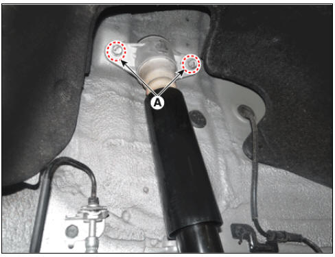
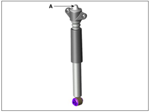
- Loosen the rear shock absorber bolts (A).
Tightening torque: 58.8 - 73.5 N*m (6.0 - 7.5 kgf*m, 43.4 - 54.2 lb*ft)
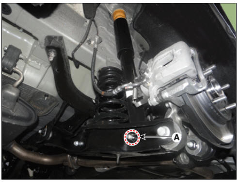
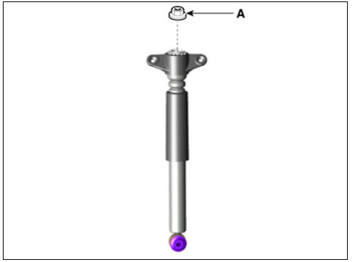
- Loosen the nut (A) and then remove the rear shock absorber.
Tightening torque: 98.0 - 117.6 N*m (10.0 - 12.0 kgf*m, 72.3 - 86.7 lb*ft)
- Install in the reverse order of removal.
Disassembly
- Remove the insulator cap (A).
- Loosen the lock nut (A).
- Install in the reverse order of removal
Inspection
- Check the rubber parts for wear and deterioration.
- Compress and extend the piston rod (A) and check that there is no abnormal resistance or unusual sound during operation.
Disposal
- Fully extend the piston rod.
- Drill a hole on the (A) section to remove gas from the cylinder.
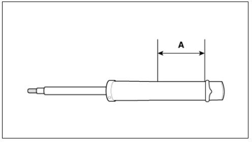
Notice
The gas released is harmless but be careful of chips that may stir up from drilling.
READ NEXT:
 Rear Lower and Upper Arm Repair procedures
Removal
Disconnect the battery negative cable.
Remove the wheel and tire.
Tightening torque: 107.9 - 127.5 N*m (11.0 - 13.0 kgf*m, 79.6 - 94.0 lb*ft)
Warning
Be careful not to damage the wheel nuts when removing the wheel and tire
Rear Stabilizer Bar Repair procedures
Removal
Disconnect the battery negative cable.
Remove the wheel and tire.
Tightening torque:
107.9 - 127.5 N*m (11.0 - 13.0 kgf*m, 79.6 - 94.0 lb*ft)
Warning
Be careful not to damage the wheel nuts when removing the wheel and
tire.
SEE MORE:
Sub High Voltage Battery
Removal
Warning
Be sure to read and follow the "General Safety Information and
Caution" before doing any work
related with the high voltage system. Failure to follow the safety
instructions may result in
serious electrical in
Tire sidewall labeling
This information identifies and describes
the fundamental characteristics of the
tire and also provides the tire identification
number (TIN) for safety standard
certification. The TIN can be used to
identify the tire in case of a recall.
Categories
- Home
- KIA Niro EV, Hybrid - Second generation - (SG2) (2021-2024) - Owner's manual
- Kia Niro - First generation - (DE) (2017-2022) - Service and Repair Manual
- Contact Us