KIA Niro: Front Radar Unit
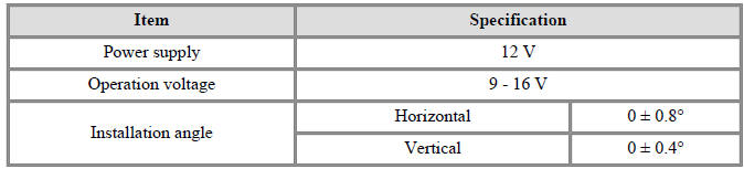
Specification
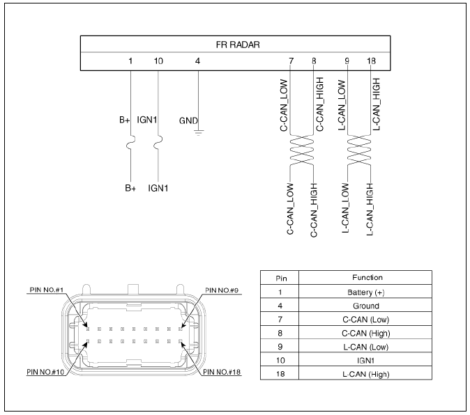
Circuit Diagram
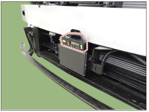
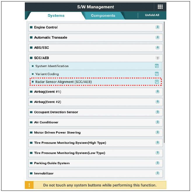
Front Radar Unit Repair Procedures
Inspection
Warning
- Put the vehicle on the level ground.
- Take out heavy luggage from the vehicles' seats or tailgate.
- Set all tires according to the specified pressure.
- Check wheel alignment.
- Check that the front surface of the front radar is clean.
- Check whether the radar cover of the bumper is dirty.
- Check the bumper appearance and accident history (visual appearance of
the vehicle, maintenance and bumper replacement
history).
→ If the vehicle has been crashed, front radar unit mounting part is highly likely to be twisted.
- Check the warning message on the cluster and DTC code.
- Check the installation angle of front radar.
Warning
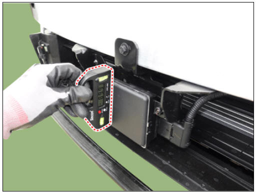
- Make sure to perform zero setting before using vertical protractor. (perform this procedure periodically)
- Be careful with +/- readings when finding true vertical using vertical protractor.
(1) Check the front radar vertical angle by using the vertical/horizontal protractor (tiltmeter).
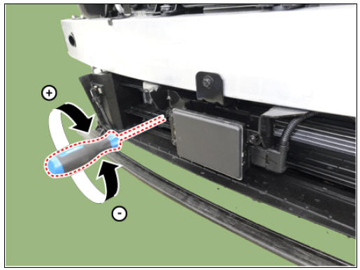
(2) If the installation angle does not meet the specification value, adjust to "target vertical angle" by turning adjusting screw of front radar.
Vertical angle : 0 +- 0.4º
(3) Check the front radar horizontal angle by using the vertical/horizontal protractor (tiltmeter).
Horizontal angle : 0 +- 0.8º
Warning
If the installation angle does not meet the specification value, inspect the deformation of bumper beam or front radar bracket.
Removal
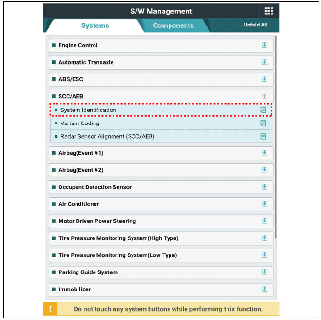
- If the front radar unit needs to be replaced, check the system identification by using the KDS.
- Remove the front bumper assembly.
(Refer to Body - "Front Bumper Assembly")
- Disconnect the connector (A) from the front radar unit.
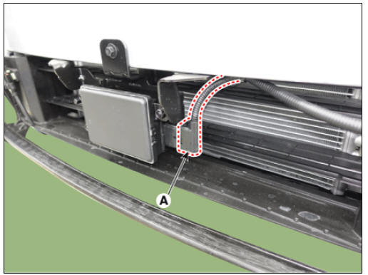
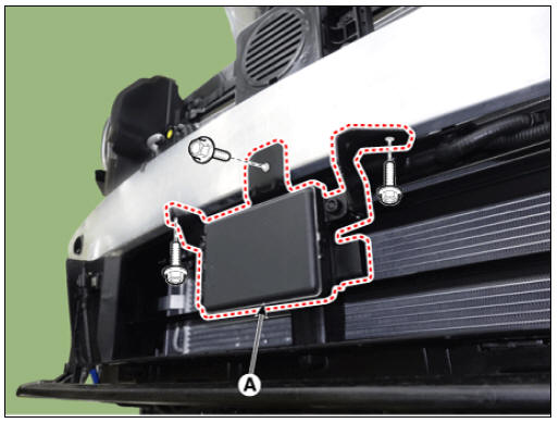
- Remove the front radar unit (A) after loosening the mounting bolts.
Installation
Warning
- Put the vehicle on the level ground.
- Take out heavy luggage from the vehicles' seats or tailgate.
- Set all tires according to the specified pressure.
- Check wheel alignment.
- Check that the front surface of the front radar is clean.
- Install in the reverse order of removal.
Warning
Check the installation angle of front radar before installing the front bumper assembly.
(Refer to Front Radar Unit - "Inspection")
- Check the installation angle of front radar before installing the front
bumper assembly.
(Refer to Front Radar Unit - "Inspection")
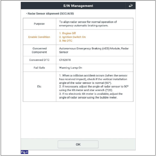
- Perform radar alignment procedure by using the KDS.
(Refer to Front Radar Unit - "Adjustment")
Adjustment
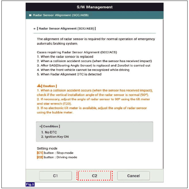
Smart Cruise Control (SCC) unit detects a forward vehicle and then recognizes the distance to the forward vehicle and the relative speed using the built-in radar sensor. In order for the radar sensor to operate correctly, it must be properly aligned parallel to the driving direction of the vehicle. So, the radar sensor alignment procedure must be carried out after the sensor is reinstalled or replaced with new one. If not performing the sensor alignment in the conditions mentioned above, the smart cruise control system may not operate correctly.
Warning
The cases that front radar installation angle checking/adjustment are needed.
- Front radar has been replaced.
- Front radar has been removed and reinstalled.
- Line up failed DTC has been occurred.
- Failure on front radar detecting and cognition function.
- failed to detect vehicle in front while functioning
- often detecting error of side lane
- often detecting error even though any object is not in front
- To perform the lateral alignment, connect the KDS with the engine started and select the "SCC Alignment".
Warning
Be sure to erase DTC before performing the lateral alignment.
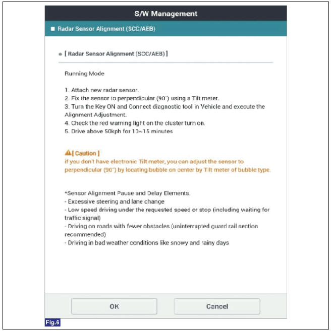
- Select "Driving Mode" to start sensor alignment.
- Drive the vehicle and check that the yellow warning light on the cluster is turned ON and then OFF.
Warning
The lateral alignment takes about 5 to 15 minutes generally but it can be shorten or extended depending on the road condition or driving condition.
Road or driving conditions for shortening the alignment :
- Driving at more than 65 km/h
- Driving on a road without curve and slope
- Driving on a thick and wide paved road
- Driving on a road where there are repetitive and fixed targets (metal materials such as street lights or guard rails)
- Driving on a dry road without rain or snow
Road or driving conditions that can interrupt the alignment process
- Driving a road with the sharp curve where the radius is within 100m
- Driving at a lower speed than suggested above or during a stop due to a red light
- Driving in a tunnel or under an overpass
- Driving in a tunnel or under an overpass
Warning
Be sure to follow the below safety guidelines while driving the vehicle for the lateral alignment :
- Observe a regulation speed
- Do not drive too fast for shortening the sensor alignment. Drive safely considering the road condition and traffic situation.
- Do not stare the KDS screen or operate the KDS while driving. Only while stopping, the KDS should be operated.
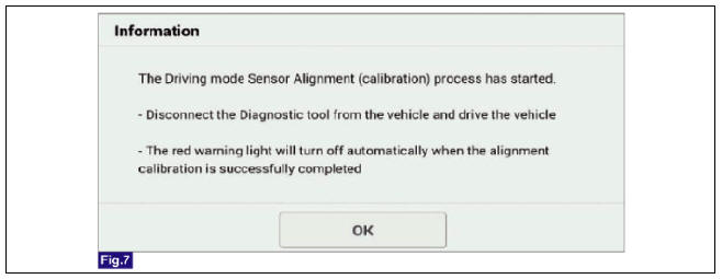
- When front radar correction is completed, the warning light will go out on the instrument cluster.
- If the alignment is not completed, check the front radar mounting angle.
- If the horizontal angle is out of the specification, check the condition of the mounting part, and if there is no abnormality, replace the front radar.
- After replacing the front radar, perform the alignment procedures again.
READ NEXT:
 Right remote control switch (Cruise control
switch)
Right remote control switch (Cruise control
switch)
Right remote control switch (Cruise control
switch)
Circuit Diagram
Right remote control switch Repair Procedures
Removal
Remove the steering wheel remote controller. (RH)
(Refer to Body Electrical System - "AVN Remote Co
Rear Corner Radar System
Rear corner radar
BCW & RCCW Indicator
Blind-Spot Collision Warning (BCW) ON/OFF switch
Description
System Interface
System Function
Blind-Spot Collision Warning (BCW)
Sends an audible warning and signal on the mirror wh
Blind-Spot Collision Warning (BCW)
BCW activation condition
(1) BCW on/off switch : On (indicated by the switch LED)
(2) Vehicle Speed : 30 - 255 km/h (20 - 158 mph)
(3) Relative vehicle speed : -10 to 255 km/h (-6 to 158 mph)
(Negative value refers to the distance of the veh
SEE MORE:
Power Relay Assembly (PRA)
PRA Operation Sequence
Description
The Power Relay Assembly (PRA) consists of the positive and negative main
relays, pre-charge relay, pre-charge resistor and
battery current sensor. It is located inside the battery pack assembly and
controls
Front Wiper Motor
Front wiper motor
Rear wiper motor
Front Wiper Motor Repair procedures
Removal
Front Wiper Motor
Remove the cowl top cover.
(Refer to Body - "Cowl Top Cover")
Disconnect the wiper motor connector (A).
Remove th
Categories
- Home
- KIA Niro EV, Hybrid - Second generation - (SG2) (2021-2024) - Owner's manual
- Kia Niro - First generation - (DE) (2017-2022) - Service and Repair Manual
- Contact Us