KIA Niro: Fuel Pressure Sensor (FPS)
Description
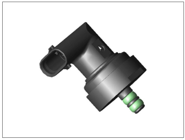
Installed on top of the low pressure fuel pump, the Fuel Pressure Sensor (FPS) measures the pressure in the low pressure fuel line.
Based on the fuel pressure measured by the FPS and the amount of fuel consumed,
the fuel pump
control module (FPCM) determines whether to activate the low pressure fuel pump.
After activating
the low pressure fuel pump, the FPS continues to send the fuel pressure to the
FPCM and the FPCM
keeps controlling the fuel flow rate using the feedback from the FPS.
Circuit Diagram
Fail-Safe Mode

Warning
If the fuel pressure sensor malfunctions, it enters fail safe mode. This means that the fuel pressure rises to match the increased level of current while the pressure in the low pressure fuel line remains static despite the rise in fuel pressure.
Terminal
Information
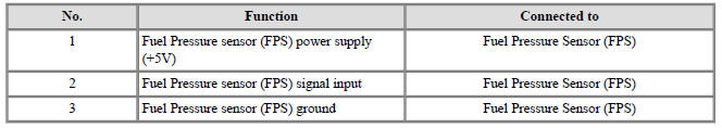
Terminal Illustration
Terminal Function
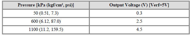
Inspection
- Connect the KDS on the Data Link Connector (DLC).
- Check that the output voltage is within the specification.
Fuel Pump Control Module (FPCM) Repair procedures
Removal
- Release the residual pressure in fuel line.
(Refer to Fuel Delivery system - "Release Residual Pressure in Fuel Line")
- Switch "OFF" the ignition and disconnect the negative (-) battery terminal.
- Remove the rear seat cushion.
( Refer to Body - "Rear Seat Assembly" )
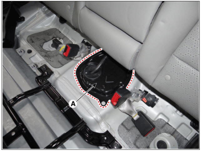
- Remove the fuel pump service cover (A).
Warning
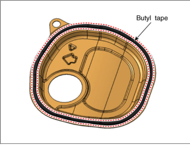
- When reinstalling a protective cover for a fuel pump, remove the existing butyl tape and apply a new one.
- Before assembling the protective cover, ensure that the
temperature of the butyl is about 30º
C using a hair dryer or a heat gun.
Warning
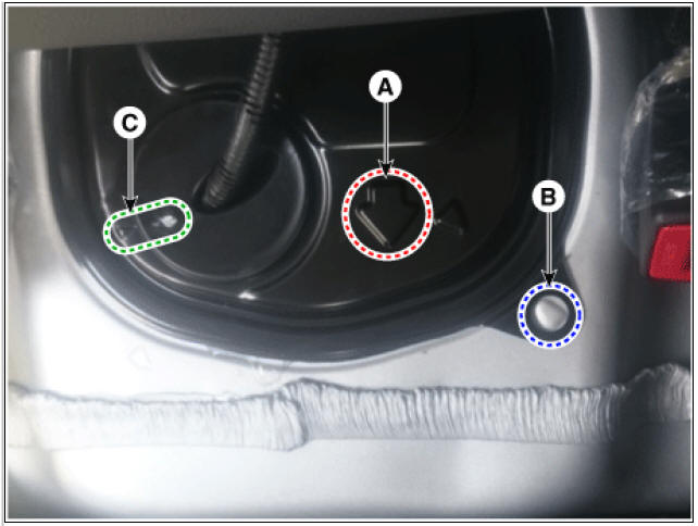
When installing the protective cover for the fuel pump, pay attention to the installation direction of the grommet and the protective cover.
- The arrow (A) should be in the forward direction of the car.
- Align the bulging part of the vehicle body (B) with the hole of the protective cover.
- Align the bulging part of the grommet (C) with the bulging part
of the protective cover.
- Disconnect the fuel pressure sensor connector (A).
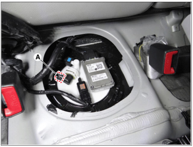
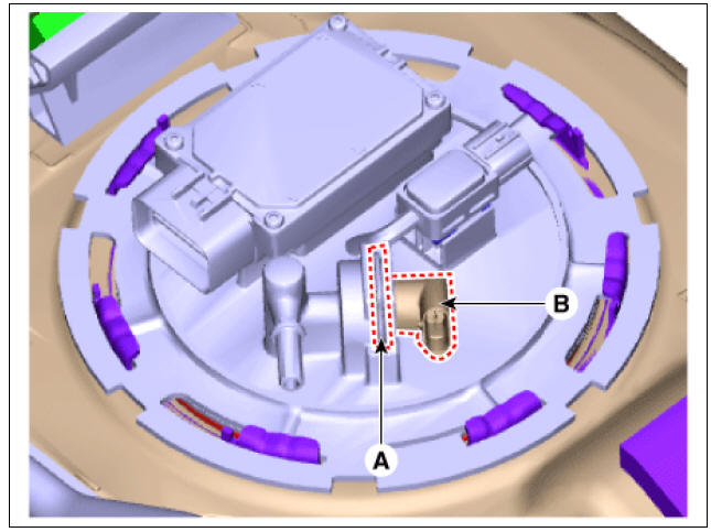
- Remove the fuel pressure sensor fixing pin (A).
- Remove the fuel pressure sensor (B) from the fuel pump.
Installation
- Install in the reverse order of removal.
READ NEXT:
 Delivery Pipe Repair procedures
Removal
Warning
In case of removing the high pressure fuel pump, high pressure fuel
pipe, delivery pipe, and injector, there
may be injury caused by leakage of the high pressure fuel. So don't do any
repair work right after engine
stops.
High Pressure Fuel Pump Repair procedures
Warning
In case of removing the high pressure fuel pump, high pressure fuel
pipe, delivery pipe, and injector, there may be injury
caused by leakage of the high pressure fuel. So don't do any repair work right
after engine stops.
Release th
Engine Clutch System
Specifications
Clutch Cover and Disc
Engine Clutch Actuator
Service Standard
Tightening Torques
Lubricants
Special Service Tools
Tool Name /
Number/
Illustration / Description
Clutch disc
guide
09411-1P000/ /Use
SEE MORE:
If an accident
occurs
WARNING
For your safety, do not touch the high
voltage cables, connectors and package
modules. High voltage components
are orange in color.
Exposed cables or wires may be visible
inside or outside of the vehicle.
Never touch the wires
Important Safety Notice
Proper service methods and repair procedures are essential for safe, reliable
operation of all motor
vehicles as well as personal safety of the operator. The service procedures and
descriptions in this shop
manual provide general directions for
Categories
- Home
- KIA Niro EV, Hybrid - Second generation - (SG2) (2021-2024) - Owner's manual
- Kia Niro - First generation - (DE) (2017-2022) - Service and Repair Manual
- Contact Us