KIA Niro: High Pressure Fuel Pump Repair procedures
Warning
In case of removing the high pressure fuel pump, high pressure fuel pipe, delivery pipe, and injector, there may be injury caused by leakage of the high pressure fuel. So don't do any repair work right after engine stops.
- Release the residual pressure in fuel line.
(Refer to the Fuel Delivery System - "Release Residual Pressure in Fuel Line").
- Switch "OFF" the ignition and disconnect the negative (-) terminal of the auxiliary 12V battery.
- Remove the air cleaner and intake hose.
(Refer to Mechanical System - "Air Cleaner")
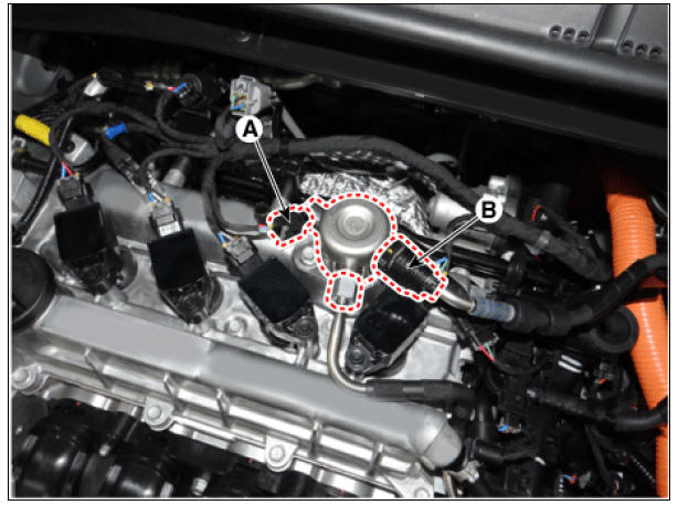
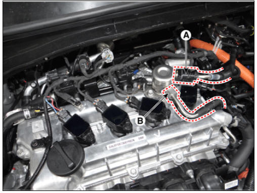
- Disconnect the fuel pressure control valve connector (A).
- Disconnect the feed tube quick-connector (B) by using a clip tool.
Warning
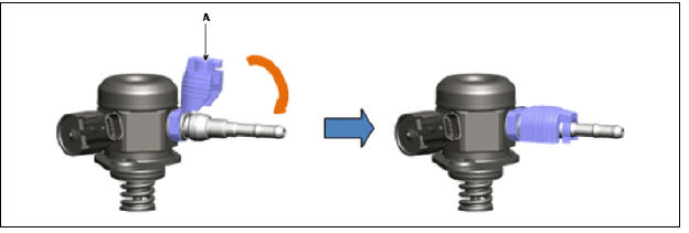
Open the clamp cover (B) before disconnecting the quick connector
(if the clip is applied). 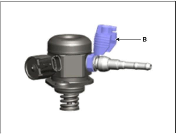
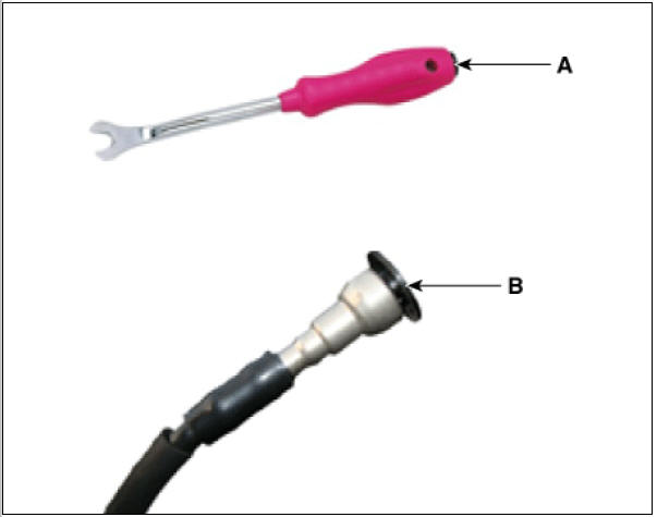
Warning
When removing the quick-connnector with the clip removing tool (A), be careful not to damage the plastic clip (B).
Damaged clip can result in fuel line leakage due to bad connection.
- Remove the high pressure fuel pipe.
(Refer to Fuel Delivery System - "Fuel Line")
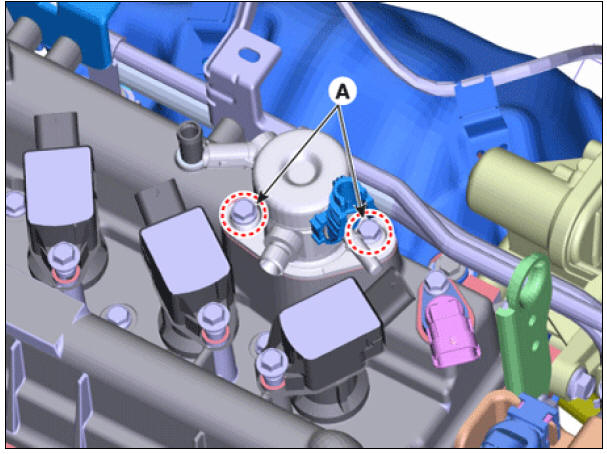
- Remove the installation bolts (A), and then remove the high pressure fuel pump (B) from the cylinder head assembly.
High pressure fuel pump mounting bolt: 12.8 - 14.7 N*m (1.3 - 1.5 kgf*m, 9.4 - 10.9 lb*ft)
Warning
Unscrew in turns the two bolts in small steps (0.5 turns). If one of the two bolts is fully unscrewed with the other still intact, the housing surface of the cylinder head may get broken due to the tension of the pump spring.
Installation
Warning
To ensure that the low pressure fuel hose quick-connector (A) is
completely engaged to the high pressure fuel pump, push it in
until it clicks. 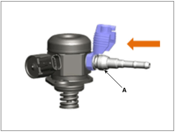
- To double check that the low pressure fuel hose is completely engaged to the high pressure fuel pump, pull it after connecting.
- Install the clamp cover (A) to tighten the quick-connector
completely.
- Be sure to install the high pressure fuel pipe (B) to the
specified torque.
- Securely inspect leakage of all fuel line connection parts at engine start condition.
Warning
Before installing the high pressure fuel pump, position the roller tappet in the lowest position by rotating the crankshaft.
Otherwise the installation bolts may get broken due to tension of the pump spring.
Warning
Do not reuse bolts.
Warning
Do not reuse high pressure fuel pipes.
Warning
When tightening the installation bolts of the high pressure fuel pump, tighten in turns the bolts in small steps (0.5 turns) after pre-tightening them by hand.
Warning
- Install the component to the specified torque.
- First hand-tighten the fasteners fully until they are not
fastened any more in order to have them inserted in place and then
completely tighten to the specified torque using a torque wrench.
If the bolts or nuts are not tightened in a straight line with the mating bolt holes or fittings, fuel leakage may occur due to broken threads.
Warning
Note that internal damage may occur when the component is dropped. In this case, use it after inspecting.
Warning
Apply engine oil to the O-ring (A) of the high pressure fuel pump,
the roller tappet (B), and the protrusion (C). Also apply
engine oil to the groove on the location where the protrusion (C) is installed.
- Install in the reverse order of removal.
Warning
Use the special service tool (SST No.: 09314-3Q100 or 09314-27130) to install the high pressure fuel pipe.
READ NEXT:
 Engine Clutch System
Specifications
Clutch Cover and Disc
Engine Clutch Actuator
Service Standard
Tightening Torques
Lubricants
Special Service Tools
Tool Name /
Number/
Illustration / Description
Clutch disc
guide
09411-1P000/ /Use
Engine Clutch Actuator
Components
Clutch disc
Clutch cover
Concentric slave cylinder
Hybrid motor assembly
Engine clutch actuator
Reservoir
Specifications
Schematic Diagrams
Harness Connector
Engine Clutch Actuator Repair procedu
Concentric Slave Cylinder Assembly Repair procedures
Removal
Remove the hybrid motor assembly.
(Refer to Hybrid Motor System - "Hybrid Motor Assembly")
Remove the engine clutch actuator.
(Refer to Engine Clutch System - "Engine Clutch Actuator")
Remove the adapter (A
SEE MORE:
Hybrid system
gauge
Power gauge
Type A
Type B
The hybrid system gauge indicates
whether the current driving condition is
fuel efficient or not.
CHARGE:
Shows that the energy made by the
vehicle is being converted to electrical
energy. (Regenerated ene
Distance to
empty
The distance to empty is displayed differently
according to the selected drive
mode in the Drive Mode Integrated Control
System.
For more information, refer to "Drive
mode integrated control system"
When destination is not set
Categories
- Home
- KIA Niro EV, Hybrid - Second generation - (SG2) (2021-2024) - Owner's manual
- Kia Niro - First generation - (DE) (2017-2022) - Service and Repair Manual
- Contact Us