KIA Niro: High Voltage Battery System / Components And Components Location / Repair Procedures
Description
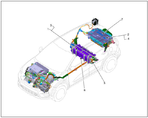
The High Voltage Battery System provides the hybrid drive motor, HSG, and electric A/C compressor
with electric energy and also reserves the electric energy generated during regeneration braking.It
consists of the battery pack assembly, BMS ECU, power relay assembly, case, control wiring, cooling
fan, and cooling ducts.
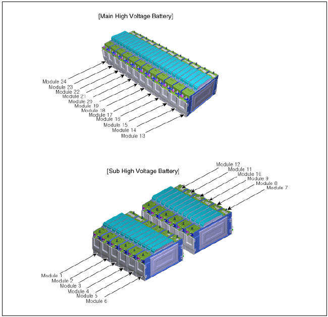
This battery is a Lithium ion Polymer Battery (LiPB) and has 96 cells (4 Cells x 24 Modules). The
voltage of each cell is 3.75V DC, so the rated voltage of this battery pack is 360V DC.
High Voltage Battery System / Components And Components Location
Components
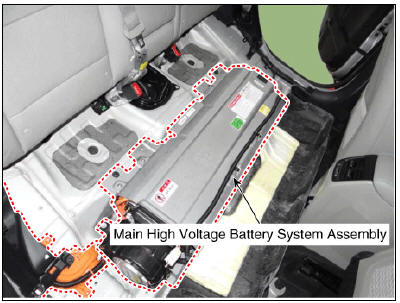
- Main High Voltage Battery System Assembly
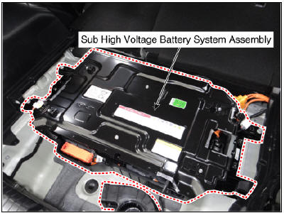
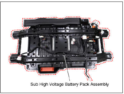
- Sub High Voltage Battery System Assembly
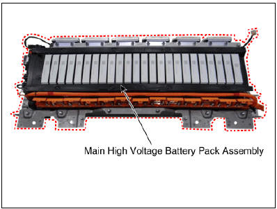
- Main High Voltage Battery Pack Assembly
- Sub High Voltage Battery Pack Assembly
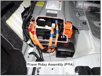
- Power Relay Assembly (PRA)
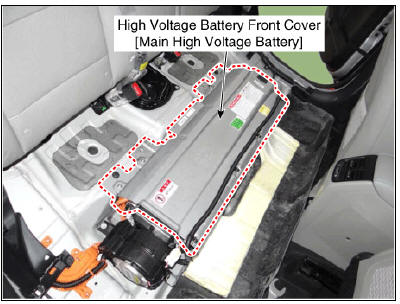
- High Voltage Battery Front Cover (Main High Voltage Battery)
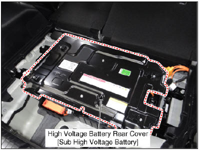
- High Voltage Battery Rear Cover (Sub High Voltage Battery)
Schematic Diagram
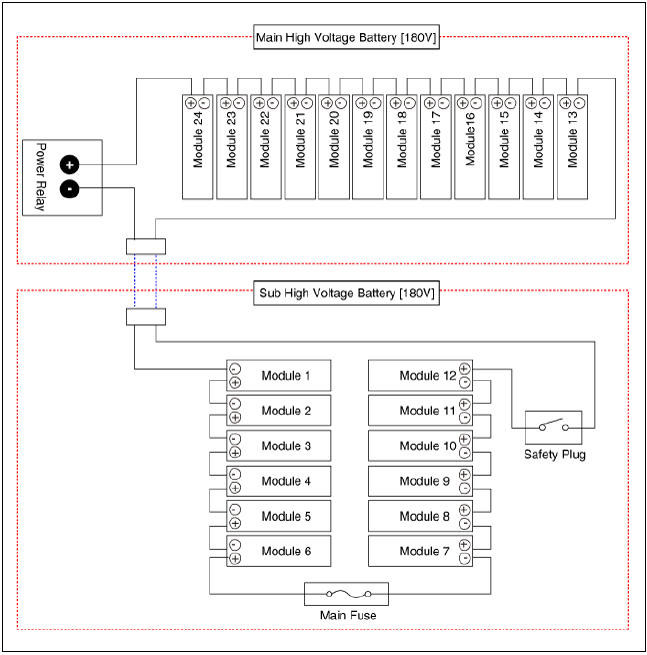
Module Number
High Voltage Battery System / Repair Procedures
Removal
Warning
- Be sure to read and follow the "General Safety Information and Caution" before doing any work related with the high voltage system. Failure to follow the safety instructions may result in serious electrical injuries.
- Be sure to read and follow the "High Voltage Shut-off Procedures" before doing any work related with the high voltage system. Failure to follow the safety instructions may result in serious electrical injuries.
- Shut off the high voltage circuit.
(Refer to Hybrid Control System - "High Voltage Shut-off Procedures")
- Remove the rear seat cushion.
(Refer to Body - "Rear Seat Assembly")
- Remove the rear door scuff trim.
(Refer to Body - "Door Scuff Trim")
- Remove the inlet cooling duct.
(Refer to High Voltage Battery Cooling System - "Cooling Duct")
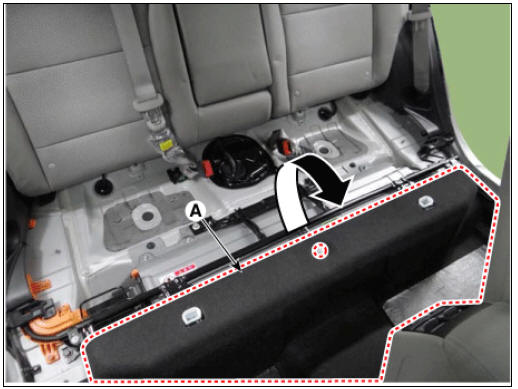
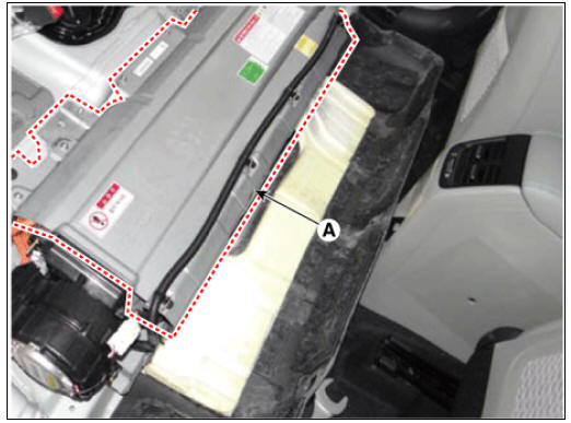
- Open the high voltage battery cushion (A) in the direction of an arrow.
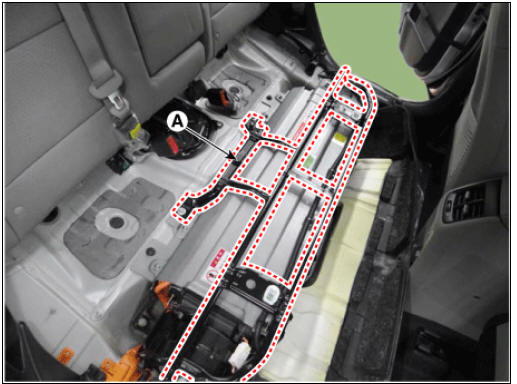
- Remove the upper frame (A) after loosening the mounting bolts and nuts.
- Remove the outlet cooling duct.
(Refer to High Voltage Battery Cooling System - "Cooling Duct")
- Remove the cooling fan #1.
(Refer to High Voltage Battery Cooling System - "Cooling Fan")
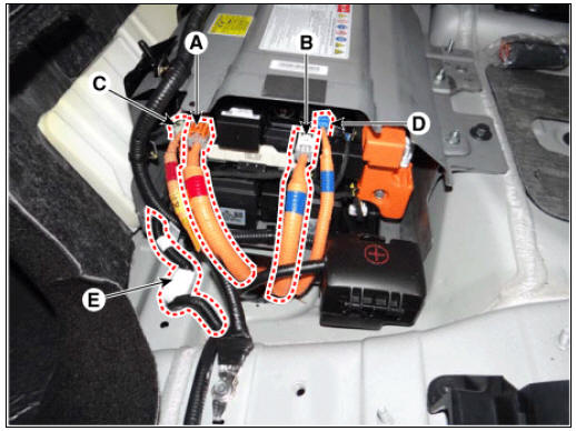
- Disconnect the inverter power connector (+) (A), inverter power connector (-} (B), OBC power connector (+) (C), OBC power connector (-) (D), BMS extension connector (E).
- Remove the luggage side trim (RH).
(Refer to Bady - " Luggage Side Trim")
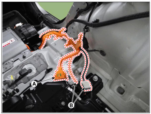
- Disconnect the high voltage cable connector (A) and BMS wiring harness connector (B) connected the sub high voltage battery.
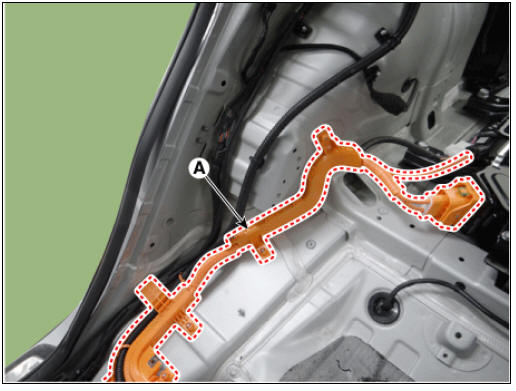
- Remove the high voltage cable (A) after loosening the mounting nuts.
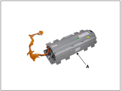
- Remove the main high voltage battery assembly (A) after loosening the mounting bolts.
READ NEXT:
 Sub Battery Pack Assembly
Warning
Be sure to read and follow the "General Safety Information and
Caution" before doing any work related with the high
voltage system. Failure to follow the safety instructions may result in
serious electrical injuries.
Be sure to
Battery Pack Assembly Repair procedures
Disassembly
Warning
Be sure to read and follow the "General Safety Information and
Caution" before doing any work related with the high
voltage system. Failure to follow the safety instructions may result in
serious electrical injuries.
SEE MORE:
Rear Cross-Traffic Collision-Avoidance Assist (RCCA)
Rear Cross-Traffic Collision-Avoidance
Assist is designed to help detect vehicles
approaching from the left and right side
while your vehicle is reversing, and warn
the driver that a collision is imminent
with a warning message and an audible
w
Remote Smart Parking Assist settings
Remote Smart Parking Assist uses vehicle
sensors to help the driver park and
exit parking spaces remotely from outside
the vehicle by controlling the steering
wheel, vehicle speed and gearshifts.
Remote Operation function may be
operate
Categories
- Home
- KIA Niro EV, Hybrid - Second generation - (SG2) (2021-2024) - Owner's manual
- Kia Niro - First generation - (DE) (2017-2022) - Service and Repair Manual
- Contact Us