KIA Niro: Sub Battery Pack Assembly
Kia Niro - First generation - (DE) (2017-2022) - Service and Repair Manual / Service Highlight / High Voltage Battery System / Sub Battery Pack Assembly
Warning
- Be sure to read and follow the "General Safety Information and Caution" before doing any work related with the high voltage system. Failure to follow the safety instructions may result in serious electrical injuries.
- Be sure to shut off the high voltage before doing any work related with the high voltage system(Refer to "High Voltage Shut-off Procedure"). Failure to follow the safety instructions may result in serious electrical injuries.
- Turn ignition switch OFF and disconnect the negative (-) battery terminal.
- Shut off the high voltage circuit.
(Refer to Hybrid Control System - "High Voltage Shut-off Procedures")
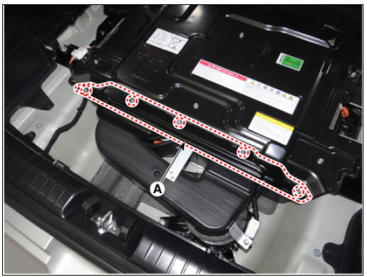
- Remove the high voltage rear cover (A) after loosening the mounting bolts.
High Voltage Battery Rear Cover mounting bolt : 7.8 - 11.8 N*m (0.8 - 1.2 kgf*m, 5.8 - 8.7 lb*ft)
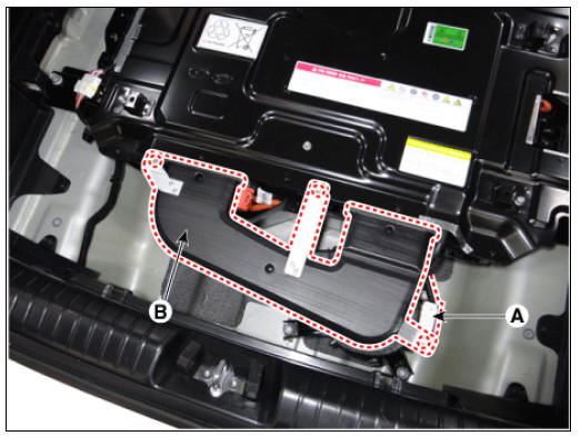
- Remove the rear outlet cooling duct (B) after loosening bolts.
Rear Outlet Cooling Duct mounting bolt : 7.8 - 11.8 N*m (0.8 - 1.2 kgf*m, 5.8 - 8.7 lb*ft)
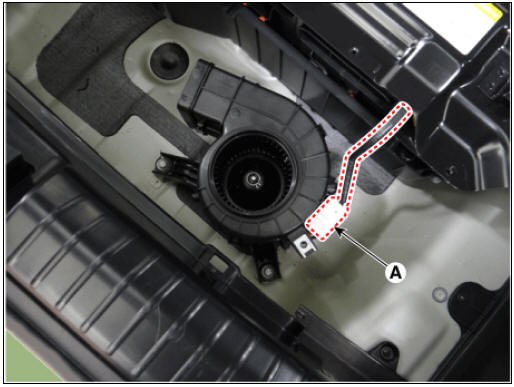
- Remove the cooling fan #2 connector (A).
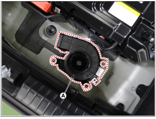
- Remove the cooling fan #2 (A) after loosening the mounting bolts.
Cooling Fan #2 mounting bolt : 7.8 - 11.8 N*m (0.8 - 1.2 kgf*m, 5.8 - 8.7 lb*ft)
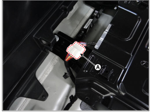
- Disconnect the BMS ECU connector (A).
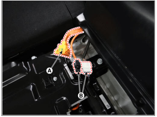
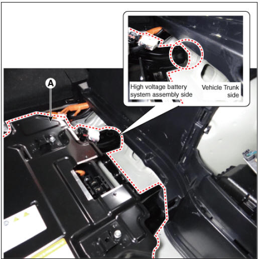
- Disconnect the high voltage cable connector (A) and BMS wiring harness connector (B) connected the main high voltage battery.
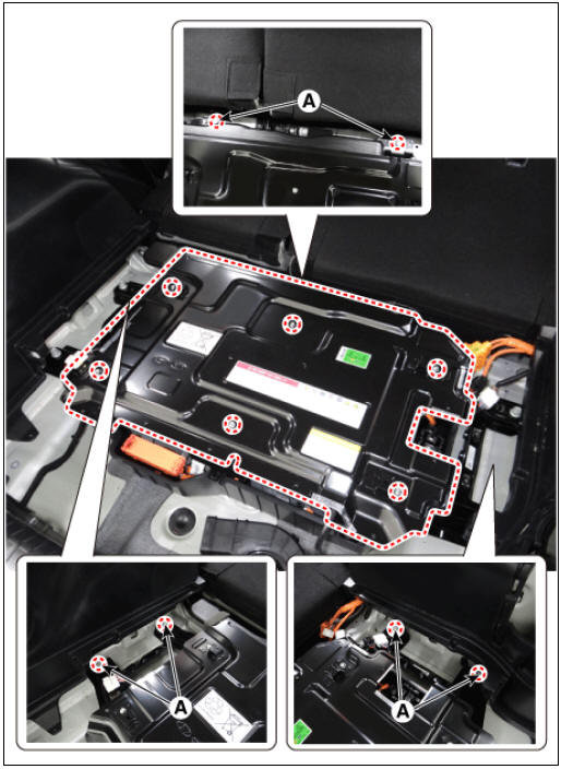
- Remove the sub high voltage battery system assembly mounting bolts (A).
Sub High Voltage Battery System Assembly mounting bolt : 54.9 - 82.4 N*m (5.6 - 8.4 kgf*m, 40.5 - 60.8 lb*ft)
- Remove the sub high voltage batter system assembly (A).
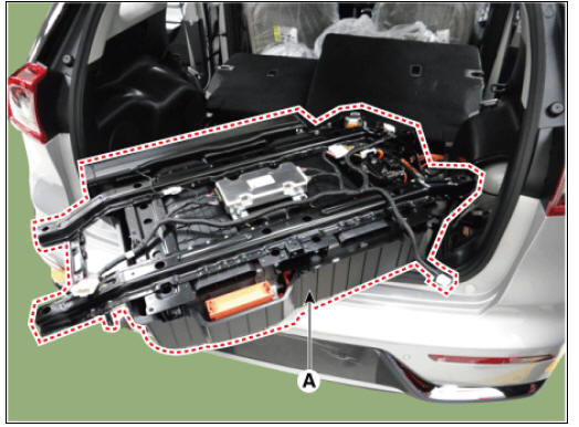
Warning
Refer to the instructions below when removing the sub high voltage battery system because of tiny places to remove. Be careful not to damage on the interior trim or rear bumper when removing the battery.
- Push the sub high votlage battery system assembly (A) to the right as much as possible.
- Remove the high voltage battery system assembly from left side.
Installation
Warning
- Be sure to read and follow the "General Safety Information and Caution" before doing any work related with the high voltage system. Failure to follow the safety instructions may result in serious electrical injuries.
- Be sure to read and follow the "High Voltage Shut-off Procedures" before doing any work related with the high voltage system. Failure to follow the safety instructions may result in serious electrical injuries.
- Install the high voltage battery pack in the reverse order of removal.
READ NEXT:
 Battery Pack Assembly Repair procedures
Disassembly
Warning
Be sure to read and follow the "General Safety Information and
Caution" before doing any work related with the high
voltage system. Failure to follow the safety instructions may result in
serious electrical injuries.
Battery Pack Assembly Troubleshooting Chart
Inspection
Warning
For SOC check, refer to "SOC Inspection"
For voltage check, refer to "Battery Voltage Inspection"
For battery voltage sensing circuit, refer to "Voltage Sensing
Circuit Inspection"
Fo
Power Relay Assembly (PRA)
PRA Operation Sequence
Description
The Power Relay Assembly (PRA) consists of the positive and negative main
relays, pre-charge relay, pre-charge resistor and
battery current sensor. It is located inside the battery pack assembly and
controls
SEE MORE:
Identification Number Locations
Identification Numbers
Identification Number Description
Vehicle Identification Number
World Manufacturer Identifier (WMI)
KNA : Passenger vehicle, MPV(Multipurpose Passenger Vehicle)/SUV(Sports
Utility Vehicle)/RV(Recreational
Cooling System
Components
Reservoir tank
Reservoir hose & pipe
Radiator
Radiator upper hose
Radiator lower hose
Radiator upper mounting bracket (RH)
Radiator upper mounting bracket (LH)
Radiator lower mounting insulator (RH)
Radiator low
Categories
- Home
- KIA Niro EV, Hybrid - Second generation - (SG2) (2021-2024) - Owner's manual
- Kia Niro - First generation - (DE) (2017-2022) - Service and Repair Manual
- Contact Us