KIA Niro: Seat Heater Switch Repair procedures
Kia Niro - First generation - (DE) (2017-2022) - Service and Repair Manual / Body Electrical System / Seat Heater / Seat Heater Switch Repair procedures
Seat Heater Switch Components and components location
Front Seat Switch
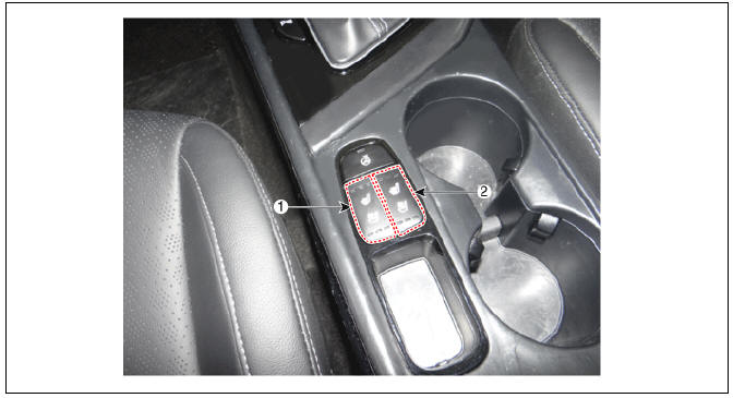
- Driver side seat heater switch
- Passenger side seat heater switch
Rear Seat Switch
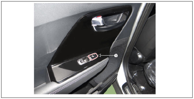
- Rear seat heater switch (LH/RH)
Description
Seat Heater Smart Control Technology
- To prevent low temperature burn, seat heater temperature will
automatically be lowered after a certain period of time.
(Low temperature burn condition: Over 30 minutes at 50ºC)
Seat Heater Smart Control Operation
1st Row Seat
- Change to "MID" after 30 minutes in "HIGH", then "LOW" after 60 minutes in "MID"
- Change to "LOW" after 60 minutes in "MID"
2nd Row Seat
- Change to "LOW" after 30 minutes in "HIGH"
Warning
- If temperature is raised manually within certain period of time after the temperature was lowered automatically, it will be lowered again soon to prevent overheating or low temperature burn.
- This is normal operating condition as a safety device.
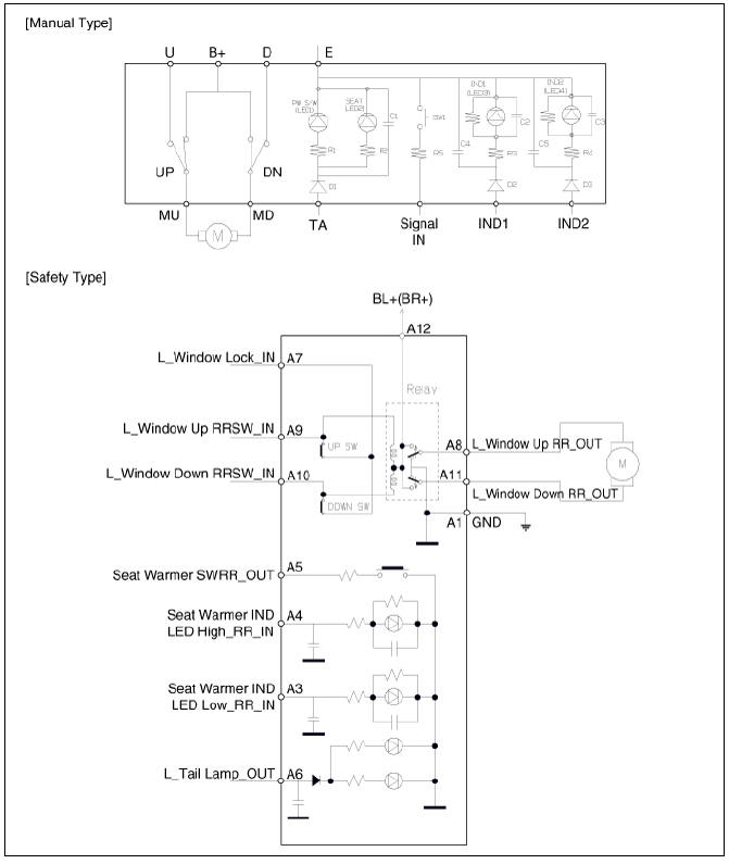
Seat Heater Switch Schematic diagrams
Front Seat Heater Switch
Rear Seat Heater Switch
Removal
Front Seat
- Remove the floor console assembly.
(Refer to Body - "Floor Console Assembly")
- Disconnect the console switch connector (A).
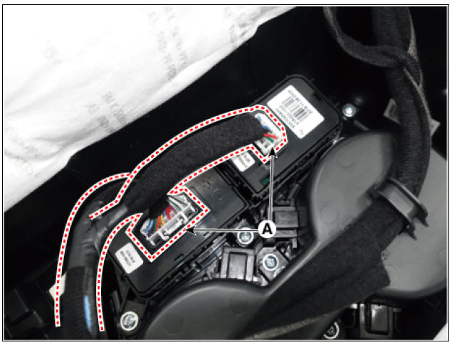
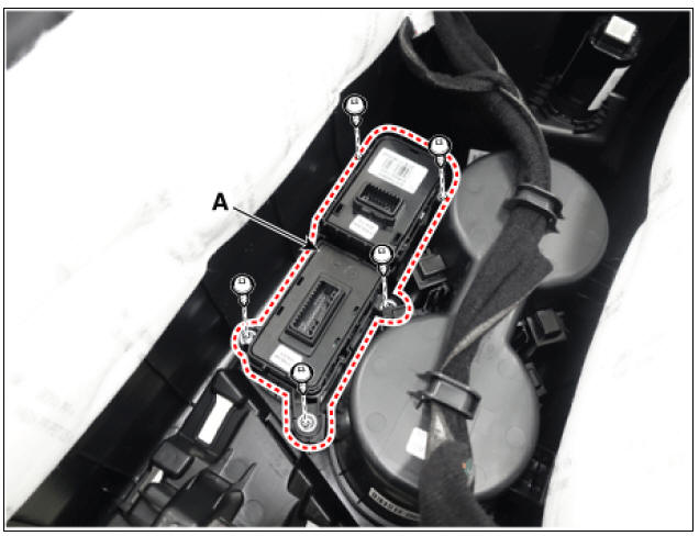
- Remove the console switch assembly (A) by loosening the screw.
Rear Seat
- Remove the rear door power window switch.
(Refer to Power Windows - "Power Window Switch")
Installation
- Install in the reverse order of removal.
READ NEXT:
 Air Ventilation Seat
Air Ventilation Seat Components and components location
Ventilation seat blower
Ventilation seat unit (Assist seat only)
Circuit Diagram
Removal
Ventilation Blower
Disconnect the negative (-) battery terminal.
Remove the fron
Lumbar Support Units
Removal
Disconnect the negative (-) battery terminal.
Remove the front seat back cover.
(Refer to Body - "Front Seat Back Cover")
Disconnect the lumbar support motor connector (A).
Separate the retaining clips (A) from t
Smart Key System
Specifications
Smart Key Unit
RF Receiver
Smart Key
Antenna
Smart Key System / Components And Components Location
Component Location (1)
Smart key unit (SMK)
Interior antenna 1
Interior antenna 2
Buzzer
Door outsid
SEE MORE:
Battery saver function
Battery saver function(Kia Niro EV)
Operation
The position lamp will turn off automatically.
Operating condition(s)
The vehicle is off and the driver's door
is opened.
INFORMATION
However, the position lamps stay ON
even wh
Driving in the rain
Rain and wet roads can make driving
dangerous, especially if you're not prepared
for the slick pavement.
Here are a few things to consider when
driving in the rain:
A heavy rainfall will make it harder to
see and will increase the dis
Categories
- Home
- KIA Niro EV, Hybrid - Second generation - (SG2) (2021-2024) - Owner's manual
- Kia Niro - First generation - (DE) (2017-2022) - Service and Repair Manual
- Contact Us