KIA Niro: Hybrid Control System / Components And Components Location
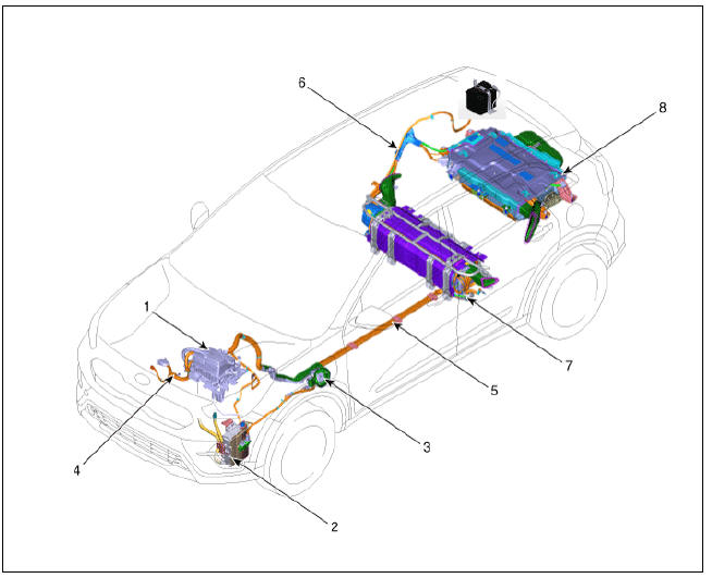
- HPCU (Hybrid Power Control Unit)
- On-Board Charger (OBC)
- Charge Port
- Power Cable (HPCU↔HSG,Electronic A/C Compressor)
- Power Cable (HPCU↔Main High Voltage Battery System)
- Power Cable (Main High Voltage Battery System ↔ Sub High Voltage Battery System)
- Main High Voltage Battery System
- Sub High Voltage Battery System
Description
The HCU (Hybrid Control Unit) controls whole hybrid systems and is connected with each control modules (ECM, TCM, MCU, BMS ECU etc.) by CAN interface. In addition this system uses the brake switch and Clutch Pressure Sensor (CPS) signals for controlling the hybrid system.
Warning
CAN interface is divided into hybrid and chassis CAN lines.
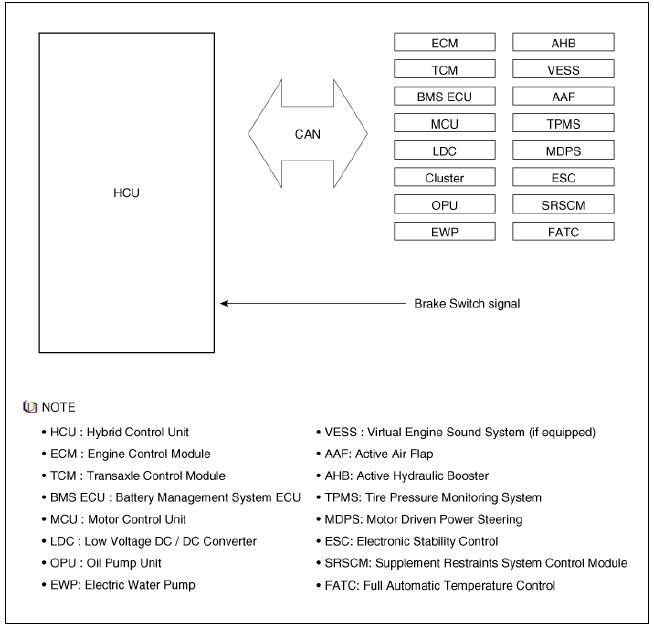
The HCU controls power & torque distribution of the engine and motor, regenerative brake, and fail-safe mode based on the vehicle information, driver's demand, engine information and high voltage battery information.
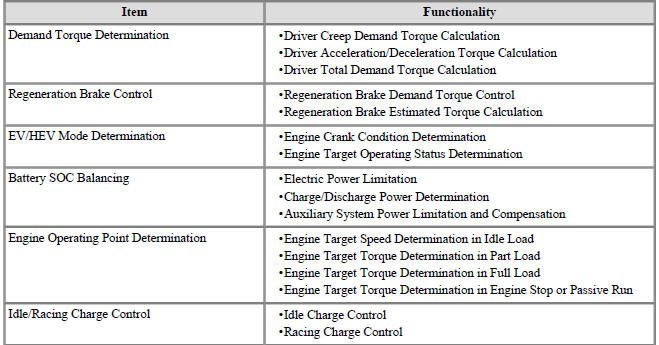
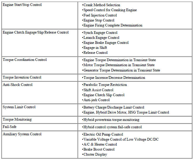
HCU Main Functionalities
Hybrid Control System / Components And Components Location
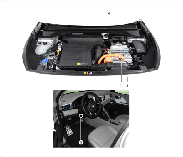
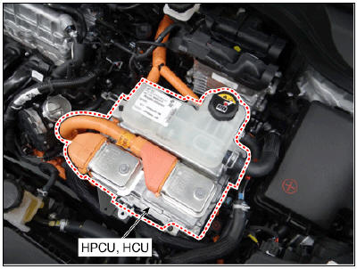
- HPCU (Hybrid Power Control Unit)
- HCU (Hybrid Control Unit)
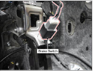
- Brake Switch
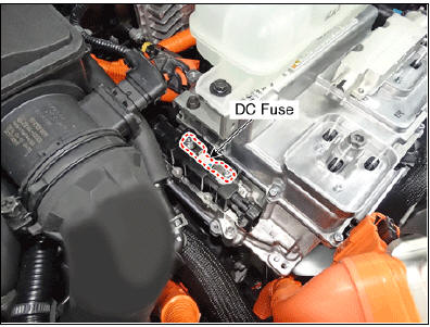
- DC Fuse
Warning
HPCU includes the HCU (Hybrid Control Unit), Inverters (for Drive Motor, HSG and Electric A/C Compressor), MCU (Motor Control Unit) and LDC (Low DC / DC Converter).
Warning
For the location of the other control modules, refer to the relevant group.
- HPCU (Hybrid Power Control Unit)
- HCU (Hybrid Control Unit)
- Brake Switch
- DC Fuse
Specification
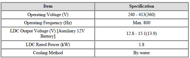
Description
The Hybrid Power Control Unit (HPCU) is an integrated power conversion unit
which consists of the
two inverters, LDC, and HCU.
Hybrid Power Control Unit (HPCU) Components and components location
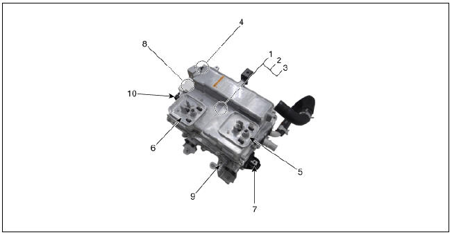
- Hybrid Control Unit(HCU) (HPCU)
- Inverter (MCU) (HPCU)
- Low Voltage DC/DC Converter (LDC) (HPCU)
- High voltage connector (↔ High voltage battery system assembly)
- High voltage connector (↔ Hybrid drive motor assembly)
- High voltage connector (↔ HSG&Electric A/C compressor)
- Low Voltage DC/DC Converter (LDC) supply output terminal (+)
- DC Fuse (30A)
- Low Voltage DC/DC Converter (LDC) ground terminal (-)
- High voltage connector (↔ HSG&Electric A/C compressor)
READ NEXT:
 Hybrid Power Control Unit (HPCU) connector and high voltage cable
Hybrid Power Control Unit (HPCU) terminal And Input/Output signal
HPCU Terminal Function
Connector (C133-S) (94Pin) : HPCU signal input and control
High Voltage Cable (C133-P) (2 Pin) : HPCU↔Power Relay Assembly
Hybrid Power Control Unit (HPCU)/ Repair procedures
Removal
Warning
Be sure to read and follow the "General Safety Information and
Caution" before doing any work related with the high voltage
system. Failure to follow the safety instructions may result in serious
electrical inju
DC Fuse
Component Location
DC Fuse
Inverter Connector (↔ Power Relay Assembly (PRA))
Inverter Connector (↔ Electric A/C compressor)
Component Location
Harness Connector
DC Fuse Repair procedures
Removal
Warning
Be s
SEE MORE:
How vehicle radio works
FM reception
AM and FM radio signals are broadcast
from transmitter towers located around
your city. They are intercepted by the
radio antenna on your vehicle. This signal
is then processed by the radio and
sent to your vehicle speakers.
Normal maintenance schedule - for Australia and New Zealand
The following maintenance services must be performed to ensure good emission
control and performance. Keep
receipts for all vehicle emission services to protect your warranty. Where both
mileage and time are shown, the frequency
of service is d
Categories
- Home
- KIA Niro EV, Hybrid - Second generation - (SG2) (2021-2024) - Owner's manual
- Kia Niro - First generation - (DE) (2017-2022) - Service and Repair Manual
- Contact Us