KIA Niro: Hybrid Power Control Unit (HPCU)/ Repair procedures
Removal
Warning
- Be sure to read and follow the "General Safety Information and Caution" before doing any work related with the high voltage system. Failure to follow the safety instructions may result in serious electrical injuries.
- Be sure to shut off the high voltage before doing any work related with the high voltage system(Refer to "High Voltage Shutoff Procedure"). Failure to follow the safety instructions may result in serious electrical injuries.
Hybrid Power Control Unit (HPCU)
- Shut off the high voltage circuit.
(Refer to Hybrid Control System - "High Voltage Shutoff Procedure")
- Remove the air cleaner assembly and air duct.
(Refer to Engine Mechanical System - "Air Cleaner")
- Remove the ECM & TCM bracket assembly.
(Refer to Engine Control/Fuel System - "Engine Control Module")
- Drain the coolant of hybrid motor cooling system.
(Refer to Hybrid Motor Cooling System - "Coolant")
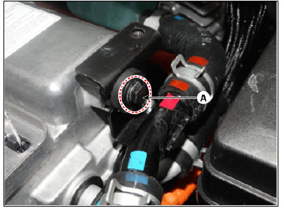
- Disconnect the motor power cable connector (A) and HSG power cable connector (B) after loosening the mounting bolts.
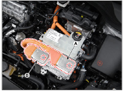
- Disconnect the power cable (A) and inverter power cable (B) from the HPCU.
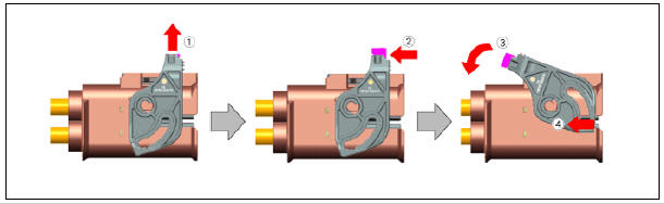
Warning
Remove the inverter power cale in the follwing order.
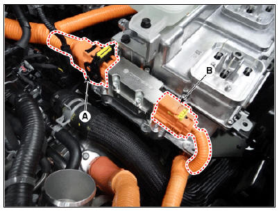
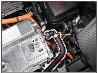
- Disconnect the HCU & inverter (MCU) connector (A).
- Disconnect the coolant outlet hose & pipe after loosening the mounting bolt (A).
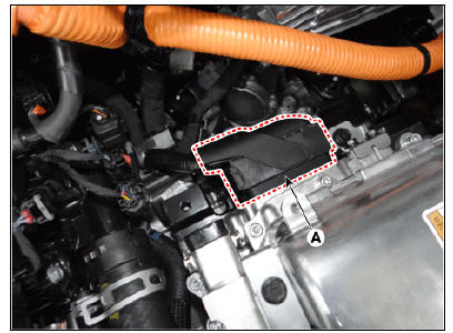
- Disconnect the coolant inlet hose quick-connector (A).
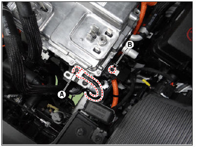
- Remove the LDC power outlet cable mounting bolt (A) and ground cable bolt (B).
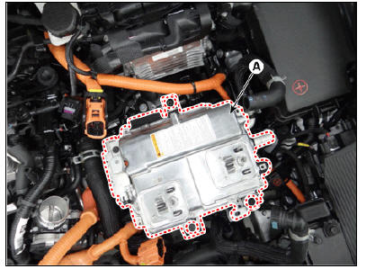
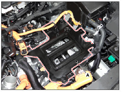
- Remove the HPCU (A) after loosening the mounting bolts.
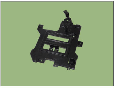
Hybrid Power Control Unit (HPCU) Tray
- Remove the hybrid power control unit.
(Refer to Hybrid Control System - "Hybrid Power Control Unit (HPCU)")
- Remove the hybrid power control unit tray (A) after loosening the mounting bolts.
Hybrid Power Control Unit (HPCU) tray mounting bolt : 21.6 - 23.5 N*m (2.2 - 2.4 kgf*m, 15.9 - 17.4 lb*ft)
Installation
Warning
Be sure to read and follow the "General Safety Information and Caution" before doing any work related with the high voltage system. Failure to follow the safety instructions may result in serious electrical injuries.
- Install the HPCU in the reverse order of removal.
- Refill the hybrid motor cooling system coolant and perform air bleeding
by using the KDS.
(Refer to Hybrid Motor Cooling System - "Coolant")
Warning
Perform HCU Variant Coding and Engine Clutch / Motor Resolver learning after replacing the HPCU.
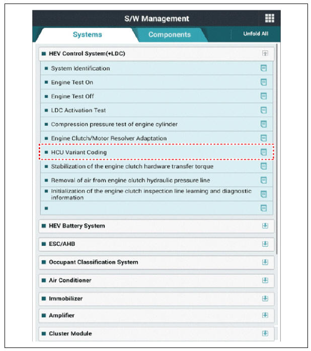
HCU Variant Coding
- Turn the ignition switch OFF.
- Connect the KDS to Data Link Connector (DLC).
Turn the ignition switch ON.
- Select "Vehicle, Model year, Engine, System".
- Select "Vehicle S/W Management".
- Select "HCU Variant Coding".
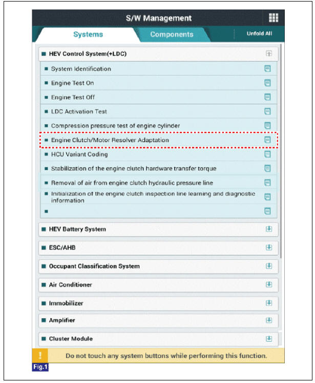
Engine clutch/motor resolver adaptation
- Turn the ignition switch OFF.
- Connect the KDS to Data Link Connector (DLC).
Turn the ignition switch ON.
- Select "Vehicle, Model year, Engine, System".
- Select "Vehicle S/W Management".
- Select "Engine clutch/motor resolver adaptation.".
HCU Terminal And Input/Output Signal

Terminal Function
Connector (C133-S)
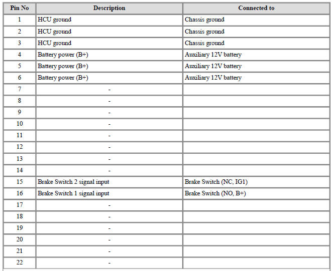
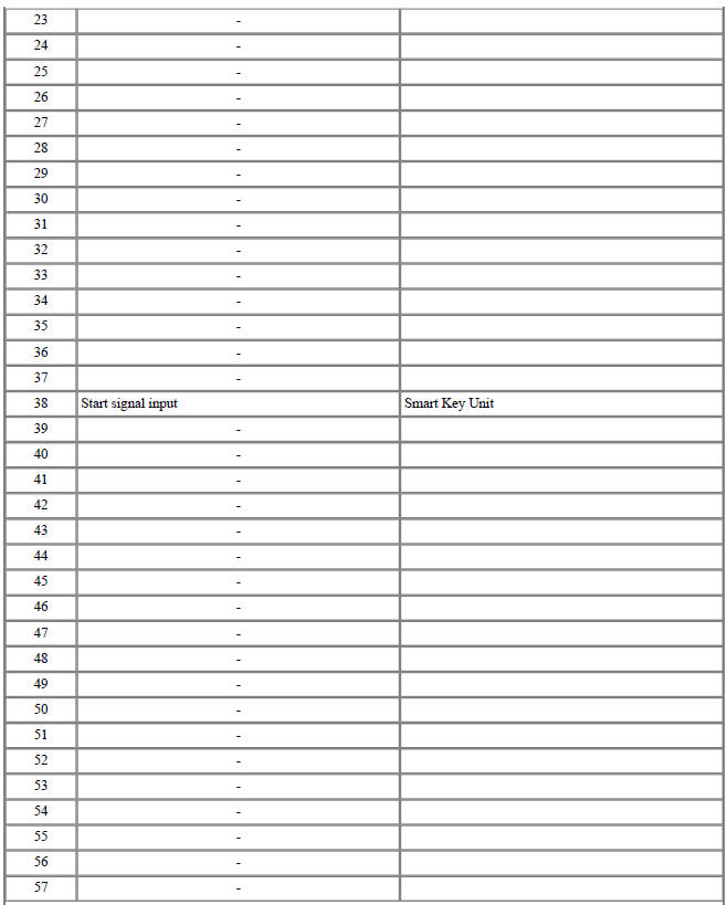
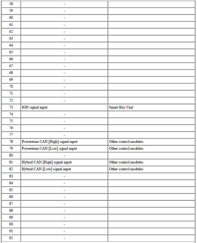

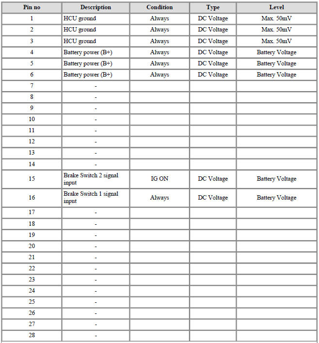
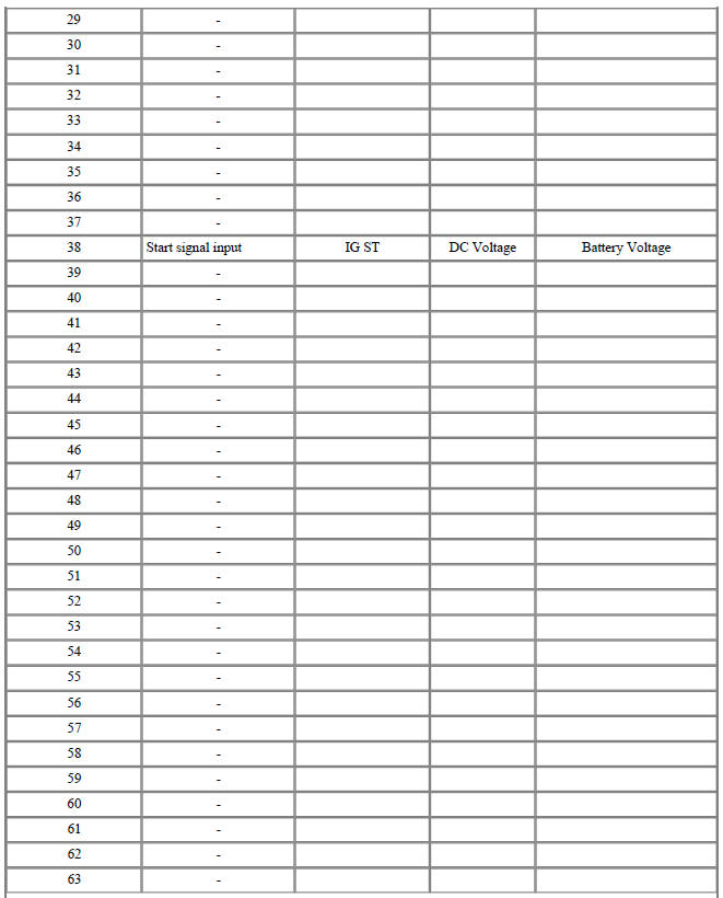
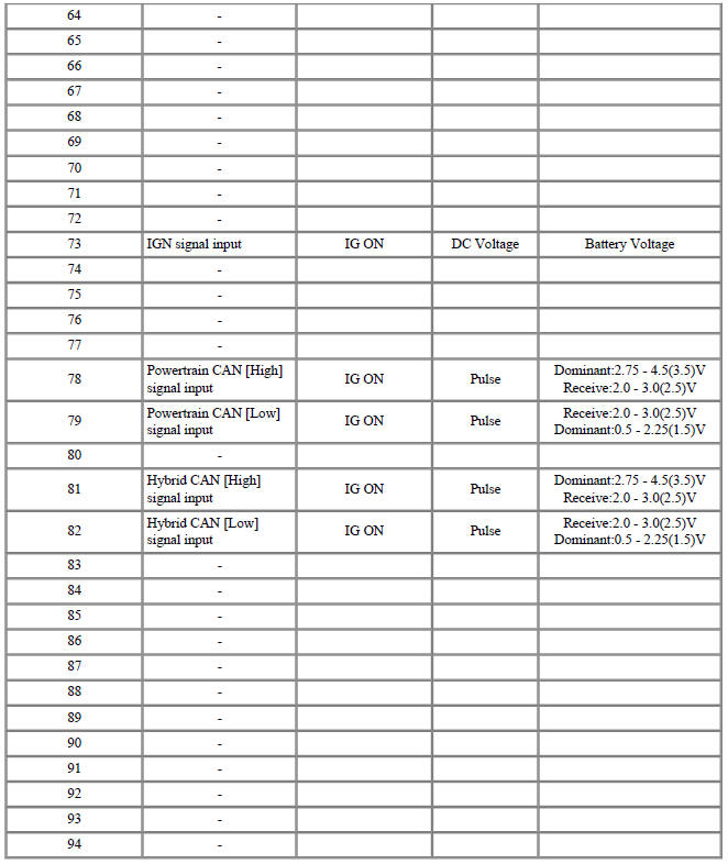
Input/Output signal
Connector (C133-S)
Circuit Diagram
Removal
Warning
- Be sure to read and follow the "General Safety Information and Caution" before doing any work related with the high voltage system. Failure to follow the safety instructions may result in serious electrical injuries.
- Be sure to read and follow the "High Voltage Shut-off Procedures" before doing any work related with the high voltage system. Failure to follow the safety instructions may result in serious electrical injuries.
- Refer to "HPCU".
Warning
The HCU is integrated into the HPCU that can't be disassembled. So refer to "HPCU" for the removal or installation procedure of the HCU.
Installation
Warning
- Be sure to read and follow the "General Safety Information and Caution" before doing any work related with the high voltage system. Failure to follow the safety instructions may result in serious electrical injuries.
- Be sure to read and follow the "High Voltage Shut-off Procedures" before doing any work related with the high voltage system. Failure to follow the safety instructions may result in serious electrical injuries.
- Refer to "HPCU".
Warning
The HCU is integrated into the HPCU that can't be disassembled. So refer to "HPCU" for the removal or installation procedure of the HCU.
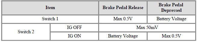
Specification
- Type : ON/OFF Switch

Description
The Brake Switch is installed on the brake pedal and linked with the HCU and
stop lamp. It sensors
the status of the brake pedal (Release, Push) and transmits the signal to the
HCU.
Circuit Diagram
Harness Connector
Removal
- Refer to Brake System - "Brake System".
Installation
- Refer to Brake System - "Brake System".
Inspection
- Refer to Brake System - "Brake System".
Adjustment
- Refer to Brake System - "Brake System".
Specification

READ NEXT:
 DC Fuse
Component Location
DC Fuse
Inverter Connector (↔ Power Relay Assembly (PRA))
Inverter Connector (↔ Electric A/C compressor)
Component Location
Harness Connector
DC Fuse Repair procedures
Removal
Warning
Be s
High Voltage Battery System / Components And Components Location
Description
The High Voltage Battery System provides the hybrid drive motor, HSG, and
electric A/C compressor
with electric energy and also reserves the electric energy generated during
regeneration braking.It
consists of the battery pack asse
SEE MORE:
Good braking practices
Be sure the parking brake is not
engaged and the parking brake indicator
light is off before driving.
The vehicle will not stop as quickly if
the brakes are wet. Apply the brakes
lightly until the braking action returns
to normal.
Do
Drive mode integrated control system
DRIVE MODE
Selecting DRIVE MODE
Operation
Press the DRIVE MODE button.
Press and hold DRIVE MODE button
to change to SNOW mode.
DRIVE MODE will change to NORMAL
mode when the vehicle is
restarted. ECO mode will be maintained
whe
Categories
- Home
- KIA Niro EV, Hybrid - Second generation - (SG2) (2021-2024) - Owner's manual
- Kia Niro - First generation - (DE) (2017-2022) - Service and Repair Manual
- Contact Us