KIA Niro: Input speed sensor | Inhibitor Switch
Kia Niro - First generation - (DE) (2017-2022) - Service and Repair Manual / DCT(Dual Clutch Transmission) System / Dual Clutch Transmission Control System / Input speed sensor | Inhibitor Switch
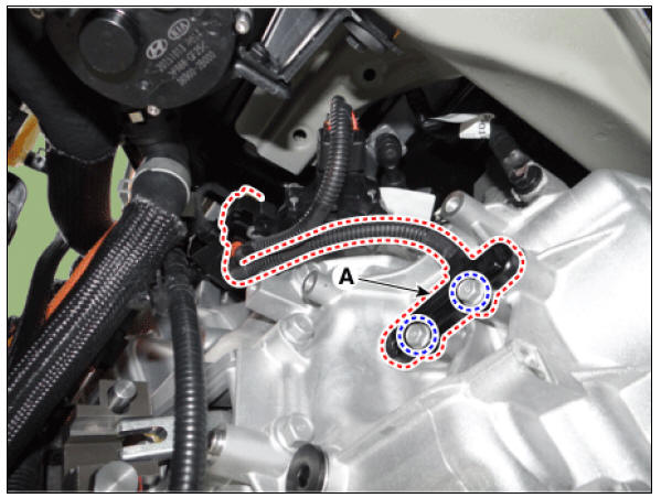
Component Location
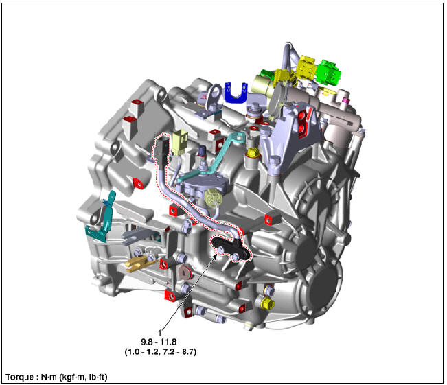
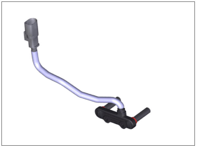
- Input speed sensor
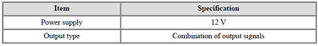
Specification
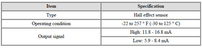
Input Speed Sensor Description and operation
Description
- The input shaft speed sensor is important in that it detects the input shaft RPM and sends this information to the Transmission Control Module (TCM).
- This data is necessary for all operations including feedback control, gear shift control and failure detection of other sensors.
Schematic Diagrams
Input Speed Sensor Repair procedures
Removal
- Remove the clutch actuator.
(Refer to Double Clutch Transmission Control System - "Clutch Actuator Assembly")
- Remove the connector from the bracket after disconnecting the connector and then remove the input speed sensor (A).
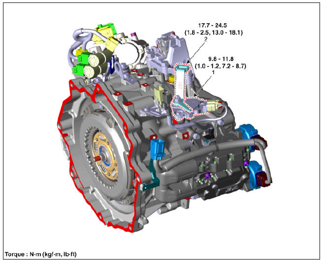
Tightening torque : 9.8 - 11.8 N*m (1.0 - 1.2 kgf*m, 7.2 - 8.7 lb*ft)
Installation
- Install in the reverse order of removal.
Warning
Before installing the input speed sensor, check the assembled state of the O-rings (A) and apply gear oil to the surface of O-rings. 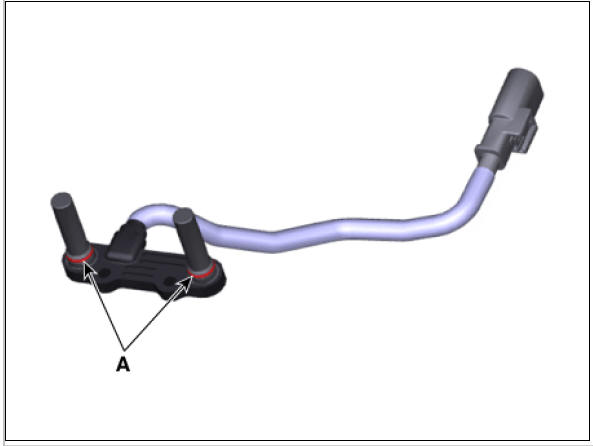
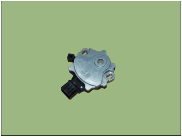
Inhibitor Switch
Component
Location
- Inhibitor switch
- Manual control lever
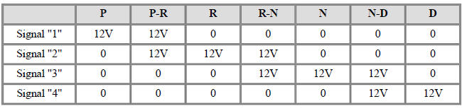
Specification
Signal Code Table
Inhibitor Switch Description and operation
Description
- The inhibitor switch is installed on top of transmission, and is connected to the shift lever through shift cable.
- Inhibitor switch signals (S1, S2, S3, S4) are transmitted to the TCM according to the driver's shift lever control.
Schematic Diagrams
Troubleshooting
READ NEXT:
 Inhibitor Switch Repair procedures
Inspection
Warning
Inspect the following items by referring to inspection flow chart.
(Refer to Inhibitor Switch - "Troubleshooting")
Check the diagnostic trouble codes (DTC) using KDS.
Inspect if "N" range setting matc
Shift Lever | Shift Cable
Components
Shift lever knob & boots
Shift lever assembly
Shift cable assembly
Shift Lever Repair procedures
Removal
Shift the gear to "N".
Remove the knob (A) by pulling it in the direction of arrow af
SEE MORE:
Crankshaft
Check the crankshaft bearing oil clearance.
(1) To check main bearing-to-journal oil clearance, remove the lower
crankcase and lower bearings.
(2) Clean each main journal and bearing with a clean shop towel.
(3) Place one strip of plastigag
Refrigerant System Service Basics (R- 134a)
For the electric compressor using high-voltage, use POE oil with high
insulation property.
Use a separate equipment (refrigerant recovery / charger) exclusive for
hybrid vehicle maintenance to prevent infusion of PAG oil of non-hybrid
v
Categories
- Home
- KIA Niro EV, Hybrid - Second generation - (SG2) (2021-2024) - Owner's manual
- Kia Niro - First generation - (DE) (2017-2022) - Service and Repair Manual
- Contact Us