KIA Niro: Multi Fuse
(Multi Fuse A, B)
- Disconnect the negative (-) battery terminal.
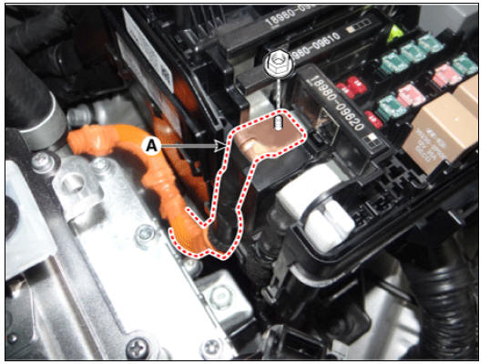
- Remove the power cable terminal (A) after loosening the nut from the engine room fuse & relay box.
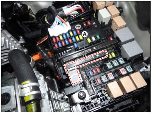
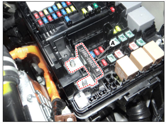
- Remove the multi fuse A (A) after pushing the hook.
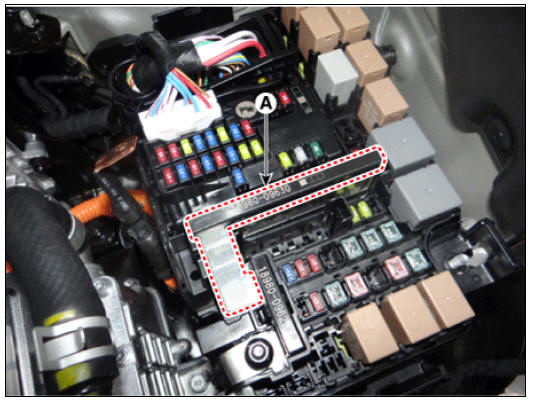
- Remove the multi fuse B (A) after pushing the hook.
(Multi Fuse C)
- Remove the multi fuse A and multi fuse B.
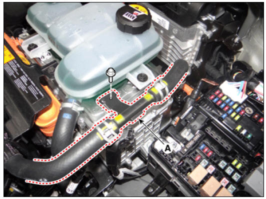
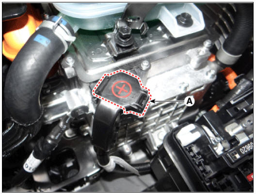
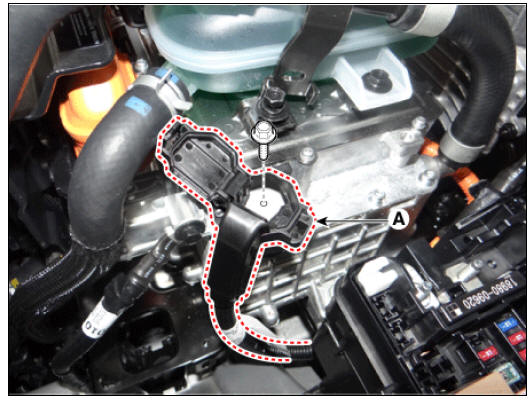
- Remove the cooling & hose bracket (A) after loosening the mounting bolt.
- Remove the power cable terminal cap (A).
- Remove the power cable terminal (A) after loosening the bolt from the HPCU.
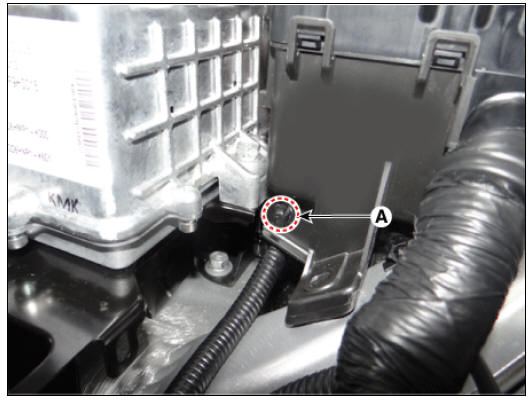
- Remove the engine room fuse & relay box power cable mounting clip (A).
- Remove the power cable terminal (A) after loosening the nut from the engine room fuse & relay box.
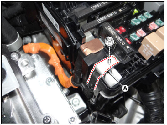
- Remove the multi fuse C (A) after pushing the hook.
Warning
- The entire multi fuse (A) has to be replaced even if only one fuse is damaged.
- When replacing it, refer to "the Engine compartment- component location" diagram to check fuse capacities and circuit arrangement.
- Use the multi fuse of the exact fuse capacity for each circuit.
READ NEXT:
 Relay Box (Passenger Compartment)
IGPM
Description
Communication Network Diagram
Integrated Gateway & Power control Module (IGPM)
Integrated Gateway & Power control Module (IGPM) is a module that performs
the function of conventional Junction Block and
Relay Box (Passenger Compartment) Repair procedures
Fuse Inspection
Check that the fuse holders are loosely held and that the fuses are
securely fixed by the holders.
Check that each fuse circuit has the exact fuse capacity.
Check the fuses for any damage.
Warning
If a fuse is to be rep
Headlamp Leveling System
Headlamp leveling actuator
Headlamp leveling switch
Connector and Terminal Function
Circuit Diagram
Headlamp Leveling Switch Repair procedures
Removal
Disconnect the negative (-) battery terminal.
Remove the crash pad low
SEE MORE:
Piston and Connecting Rod Repair procedures
Disassembly
Warning
Be sure to read and follow the "General Safety Information and
Caution" before doing any work related
with the high voltage system. Failure to follow the safety instructions may
result in serious electrical
injuries
Specifications & Consumer information (Kia Niro EV)
Dimensions
Electric vehicle specifications
OBC: On-Board Battery Chargers
Volume and weight
Available front trunk weight
Air conditioning system
Please contact a professional workshop for more details. Kia recommends to
co
Categories
- Home
- KIA Niro EV, Hybrid - Second generation - (SG2) (2021-2024) - Owner's manual
- Kia Niro - First generation - (DE) (2017-2022) - Service and Repair Manual
- Contact Us