KIA Niro: Relay Box (Passenger Compartment)
IGPM
Description
Communication Network Diagram
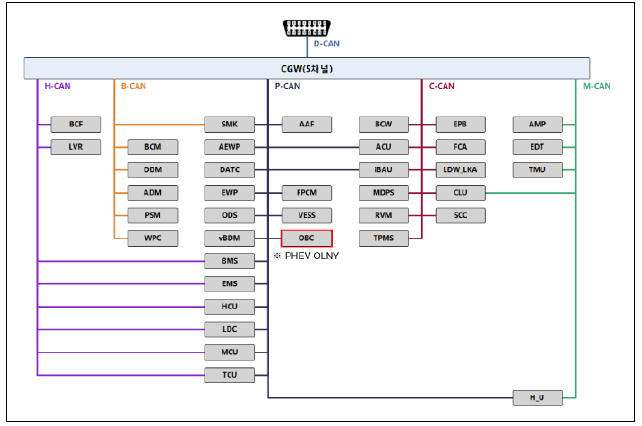
Integrated Gateway & Power control Module (IGPM)
Integrated Gateway & Power control Module (IGPM) is a module that performs the function of conventional Junction Block and some functions of BCM.
It controls various components including lamps by using CAN communication and IPS (replacing the function of fuse and relay) or ARISU.
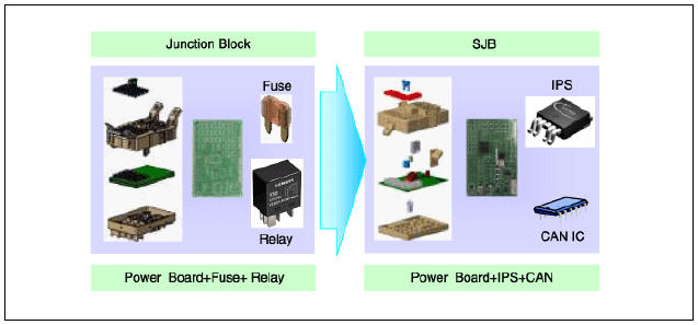
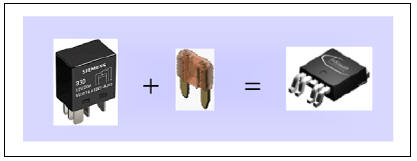
IPS stands for Intelligent Power Switch, which uses the semiconductor
technology to replace the current role of fuse and relay. (The
IPS chip has two functions: 1) the high current-based component control; 2)
component protection from overcurrent.)
Warning
The advantages of IPS are as follows:
- Reduce relay and consequently decrease weight and volume
- Remove the relay operation noise
- No need to replace fuses and increase the product life
- Capable to diagnose faulty parts
IGPM control entry
- Switch signal input
(1) Assist the door switch
Driver's seat belt switch
Rear left door switch
Rear right door switch
IGN1 switch
IGN2 switch
Brake fluid sensor
Tailgate open switch
Tailgate lid handle switch
Hazard lamp switch
Head lamp low beams switch
Hood switch
Left front / rear turn signal switch
Right front / rear turn signal switch
Parking brake switch
Driver the door lock/unlock control status
Assist the door lock/unlock control status
Rear left the door lock/unlock status
Rear right the door lock/unlock status
Driver the door switch
Driver the door key lock switch
Driver the door key unlock switch
Driver the door power window lock switch
Driver the door power window unlock switch
(2) IPS&ARISU
Left Head lamp low beams
Right Head lamp low beams
Left Head lamp high beams
Right Head lamp high beams
Room lamp
Exterior left tail lamp
Exterior right tail lamp
Left front / rear turn signals
Right front / rear turn signals
Body resistance cut control
Front left static bending light
Front right static bending light
(3) Relay Control
Tailgate lid relay
Door lock/unlock relay
Power window wake-up relay
- IGPM protection
(1) PCL (Programmable Current Limit) functions
- PCL replaces the junction block function of protecting wires.
- How to operate : If the lamp current exceeds the standard level, cut off the current to protect the lamp.
- Lamp cut off time : 300ms or less.
- Applied components: all lamp components controlled by IGPM
- Output the error code according to the error detection conditions.
(2) OCL (Open Current Limit)
- OCL detects the lamp open state and informs the user of it.
- How to operate: Detect the current of the lamp and if it is below the standard level, change the lamp operation.
- Applied components: 4 turn signal lamps.
- Output the error code according to the error detection conditions
- IGPM fail safe function
(1) When the MCU is out of order (not operating due to a physical or electrical shock from the outside), and IGN2 and head lamp low switch are on, IGPM forces the head lamp low and exterior/interior lamps to turn on in order to secure the driver's safety.
(2) When the data transmission/reception fails due to a failed CAN communication line connected with IGPM module (disconnection of both high and low line, high/low BAT short, high/low GND short), the head lamp low and interior/exterior tail lamps are forced to turn on if IGN2 is on and the head lamp low switch is on.
- Auto Cut System of Dark Current
(1) Description : It cuts automatically power to be provided with components for reducing useless dark current according to vehicle state.
(2) IGPM had 3 modes, "Normal Mode", "Sleep Mode", "Power Off Mode". Auto cut of dark current practice in "Sleep Mode".
- "Sleep" condition: IG OFF, consistent state of the input switch during a certain time, non-operation state of the CAN network.
- "Sleep" deactivation condition: switch inputs, operation state of the CAN network, KEY ON, POWER ON.
- "Power off" condition: In the dark current automatic cutoff function, the timer set for cutting the power load runs out.
- "Normal Mode" : IGPM function normally activates.
- "Sleep Mode" : It is low power mode and activates for reducing electricity consumption of IGPM. Auto cut of dark current function activates.
- "Power OFF Mode" : Power of MCU and circumferential circuit is cut for minimizing electricity consumption. Operation stops.
(3) The explanation - The auto cut of dark current
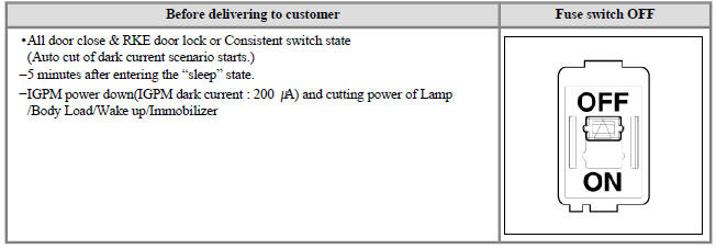
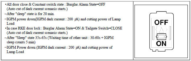
(4) Possible problems in case of the fuse switch setting errors
: If a fuse switch is set to OFF(Before delivering to customer) by a customer or technician and auto cut function of dark current activates, the following problems may occur.
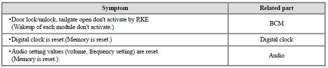
* If fuse switch OFF(before delivering to customer) is set, power of BCM, Digital clock and audio is shut off.
READ NEXT:
 Relay Box (Passenger Compartment) Repair procedures
Fuse Inspection
Check that the fuse holders are loosely held and that the fuses are
securely fixed by the holders.
Check that each fuse circuit has the exact fuse capacity.
Check the fuses for any damage.
Warning
If a fuse is to be rep
Headlamp Leveling System
Headlamp leveling actuator
Headlamp leveling switch
Connector and Terminal Function
Circuit Diagram
Headlamp Leveling Switch Repair procedures
Removal
Disconnect the negative (-) battery terminal.
Remove the crash pad low
Horn
Specifications
Horn switch
Horn relay (Built - in Metal Core Block PCB)
Horn (Low pitch)
Horn (High pitch)
Clock spring
Body Electrical System / Horn / Repair Procedures
Removal
Remove the front bumper cover.
(Refer to Bod
SEE MORE:
Characteristics of Dual clutch
transmission
The dual clutch transmission has seven
forward speeds and one reverse
speed.The individual speeds are
selected automatically when the shift
lever is in the D (Drive) position.
The dual clutch transmission can be
thought of as an automatical
For best battery service (Kia Niro EV)
Keep the battery securely mounted.
Keep the top of the battery clean and
dry.
Keep the terminals and connections
clean, tight, and coated with petroleum
jelly or terminal grease.
Immediately rinse any electrolyte
spilled from the
Categories
- Home
- KIA Niro EV, Hybrid - Second generation - (SG2) (2021-2024) - Owner's manual
- Kia Niro - First generation - (DE) (2017-2022) - Service and Repair Manual
- Contact Us