KIA Niro: Pressure Source Unit Repair procedures
Pressure Source Unit Components and components location
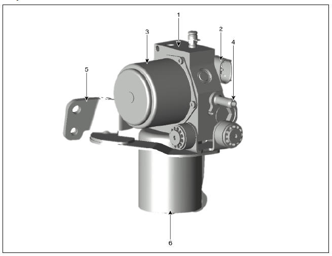
Components
Warning
PSU (Presser Source Unit) must not be disassembled.
- Pressure Source Unit (PSU)
- Pressure Source Unit (PSU) connector
- Motor
- Filler adapter
- Bracket
- Accumulator
Pressure Source Unit Repair procedures
Removal
Warning
The following section describes how to diagnose faults using a diagnostic instrument.
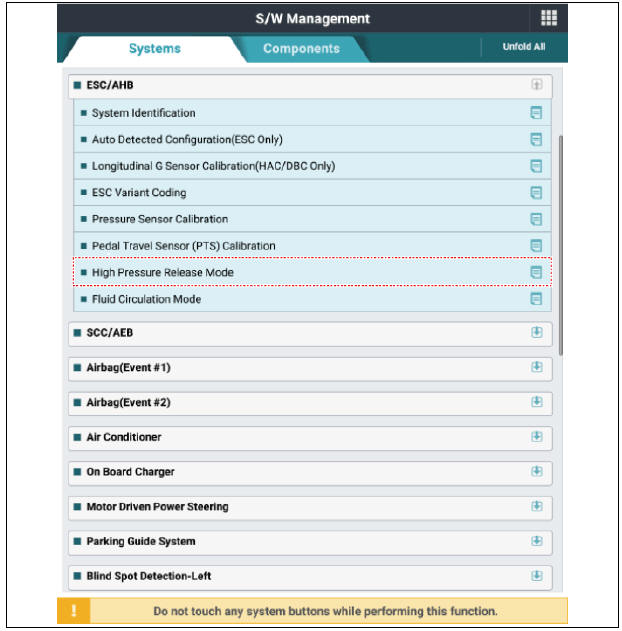
1) Connect self-diagnosis connector (16pins) located under the driver side crash pad to self-diagnosis device, and then turn the self-diagnosis device after key is ON.
2) Select the "vehicle model" and "ESC/AHB" on KDS vehicle selection screen.
3) Select the "High Pressure Release Mode" on KDS screen, then select OK.
4) Proceed with the test according to the screen instructions.
- Turn ignition switch OFF and disconnect the negative (-) battery terminal.
- Remove the air cleaner assembly.
(Refer to Engine Mechanical System - "Air Cleaner")
- Remove the brake fluid from the master cylinder reservoir with a syringe.
Warning
Do not spill brake fluid on the vehicle as it may damage the paint. If brake fluid comes in contact with the paint, wash off immediately with water.
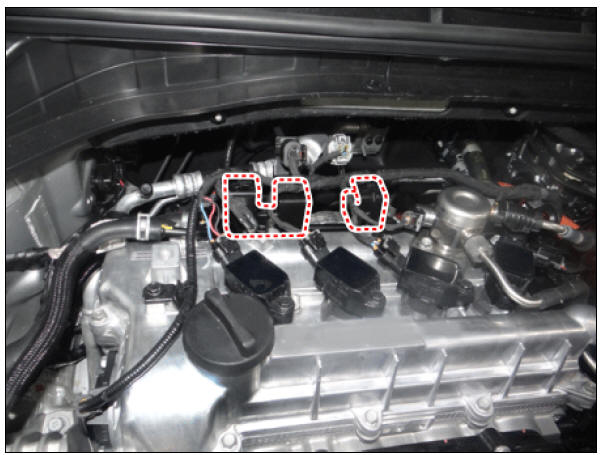
- Remove the connector and wire ring bracket.
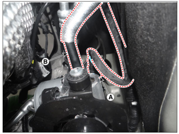
- Loosen the pressure source unit (PSU) flare nut (A) and then remove the tube.
Tightening torque: 12.7 - 16.7 N*m (1.3 - 1.7 kgf*m, 9.4 - 12.3 lb*ft)
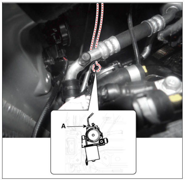
- Disconnect the pressure source unit (PSU) connector (A) and hose (B).
- Remove the sub frame.
(Refer to Suspension System - "Sub Frame")
- Loosen the nuts and bolt and then remove the pressure source (PSU).
Tightening torque: 19.6 - 29.4 N*m (2.0 - 3.0 kgf*m, 14.5 - 21.7 lb*ft)

Installation
- Installation is the reverse of removal.
- Check the brake pedal operation.
- After filling the brake fluid in the reservoir, perform the air bleed.
(Refer to the Brake system - "Brake Bleeding Procedure")
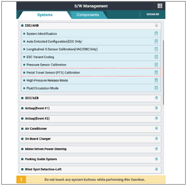
- Conduct the pedal traval sensor (PTS) calibration.
(Refer to the Brake System - "Brake Pedal")
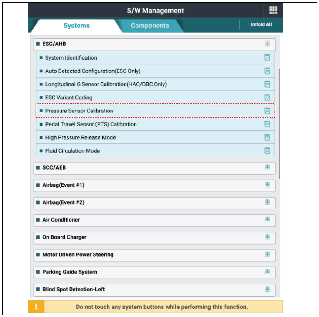
- Conduct the pressure sensor calibration.
Diagnostic Procedure Using a Diagnostic Instrument
The following section describes how to diagnose faults using a diagnostic instrument.
- Connect self-diagnosis connector (16pins) located under the driver side crash pad to self-diagnosis device, and then turn the selfdiagnosis device after key is ON.
- Select the "vehicle model" and "ESC/AHB" on KDS vehicle selection screen.
- Proceed with the test according to the screen instructions.
Pressure Sensor Calibration
Pedal Travel Sensor (PTS) Calibration
READ NEXT:
 The Air Cleaner
Element
The Air Cleaner
Element
Inspection
Remove the air cleaner element.
Check that the air filter is excessively dirty.
If the air filter is excessively dirty, replace the air cleaner element.
If the air cleaner element needs to be cleaned, blow compressed air as
Battery Terminal
Move back and forth to check that the battery terminals (A) are loose or
corroded.If the terminals are corroded,
clean them.
If battery positive connection is loose, disconnect ground(GND) cable first
before attempting to remove
SEE MORE:
Servicing The Electrical System
Prior to servicing the electrical system, be sure to turn off the
ignition switch and disconnect the
battery ground cable.
Warning
In the course of MFI or ELC system diagnosis, when the battery cable
is removed, any
diagnostic trouble
Intelligent Speed Limit Assist malfunction and limitations
Intelligent Speed Limit Assist malfunction
A: Check Speed Limit system
When Intelligent Speed Limit Assist is not
working properly, the warning message
will appear on the cluster for several seconds,
and the master ( ) warning light
will ap
Categories
- Home
- KIA Niro EV, Hybrid - Second generation - (SG2) (2021-2024) - Owner's manual
- Kia Niro - First generation - (DE) (2017-2022) - Service and Repair Manual
- Contact Us