KIA Niro: Rear Cross Member Repair procedures
Removal
- Disconnect the battery negative cable.
- Remove the wheel and tire.
Tightening torque: 107.9 - 127.5 N*m (11.0 - 13.0 kgf*m, 79.6 - 94.0 lb*ft)
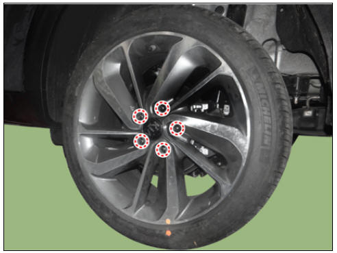
Warning
Be careful not to damage the wheel nuts when removing the wheel and tire.
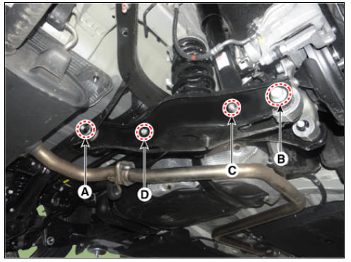
- Loosen the rear lower arm bolt (A,B), rear shock absorber bolt (C) and stabilizer link bolt (D) and then remove the rear lower arm.
Tightening torque: (A) 137.3 - 156.9 N*m (14.0 - 16.0 kgf*m, 101.3 - 115.7 lb*ft) (B) 107.9 - 117.7 N.m (11.0 ~ 12.0 kgf.m, 79.6 - 86.8 lb-ft) (C ) 98.0 - 117.6 N*m (10.0 - 12.0 kgf*m, 72.3 - 86.7 lb*ft) (D) 19.6 - 29.4 N*m (2.0 - 3.0 kgf*m, 14.5 - 21.7 lb*ft)
Warning
Set up the transmission jack under the lower arm in order to remove the shock absorber in no-load condition.
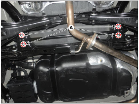
- Loosen the bolts (A) and then remove the rear stabilizer bar.
Tightening torque: 44.1 - 53.9 N*m (4.5 - 5.5 kgf*m, 32.5 - 39.8 lb*ft)
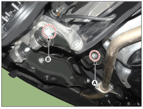
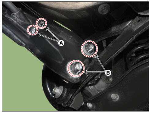
- Loosen the bolts (A,B) and then remove the rear assist arm.
Tightening torque: (A) 137.3 - 156.9 N*m (14.0 - 16.0 kgf*m, 101.3 - 115.7 lb*ft) (B) 107.9 - 117.7 N.m (11.0 ~ 12.0 kgf.m, 79.6 - 86.8 lb-ft)
- Loosen the wheel speed sensor bracket bolt (A) from the rear upper arm.
Tightening torque: 6.8 - 10.7 N*m (0.7 - 1.1 kgf*m, 5.0 - 7.9 lb*ft)
- Loosen the bolt from the upper arm.
Tightening torque: 137.3 - 156.9 N*m (14.0 - 16.0 kgf*m, 101.3 - 115.7 lb*ft)
- Loosen the upper arm bolt and then remove the upper arm.
Tightening torque: 137.3 - 156.9 N*m (14.0 - 16.0 kgf*m, 101.3 - 115.7 lb*ft)
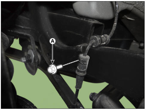
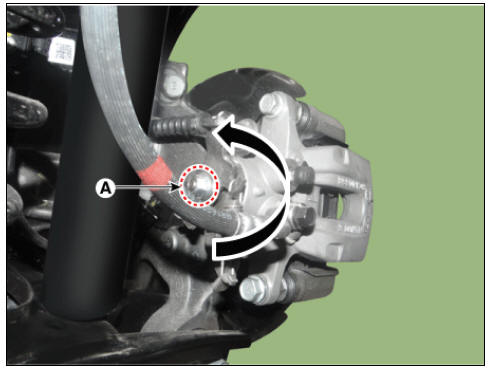
- Remove the parking brake cable pin (A).
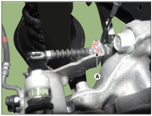
- Rotates the nut (A) in the counterclockwise direction and then remove the parking cable.
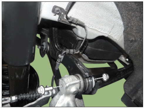
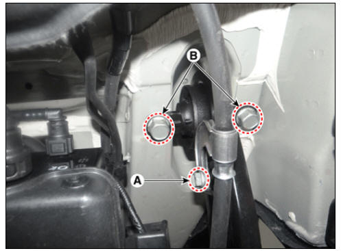
- Loosen the parking brake cable nuts (A) and trailing arm nuts (B).
Tightening torque: (A) 6.8 - 10.7 N*m (0.7 - 1.1 kgf*m, 5.0 - 7.9 lb*ft) (B) 137.3 - 156.9 N*m (14.0 - 16.0 kgf*m, 101.3 - 115.7 lb*ft)
- Remove the rear axle.
(Refer to Driveshaft and axle - "Rear Hub - Carrier")
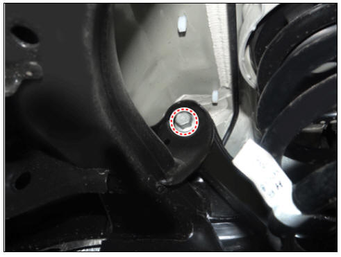
- Loosen the parking brake cable bracket bolt (A) and trailing arm bolts (B) and then remove the trailing arm.
Tightening torque: (A) 8.8 - 13.7 N*m (0.9 - 1.4 kgf*m, 6.5 - 10.1 lb*ft) (B) 98.0 - 117.6 N*m (10.0 - 12.0 kgf*m, 72.3 - 86.7 lb*ft)
- Remove the rear muffler.
(Refer to Engine Mechanical System - "Mulffler")
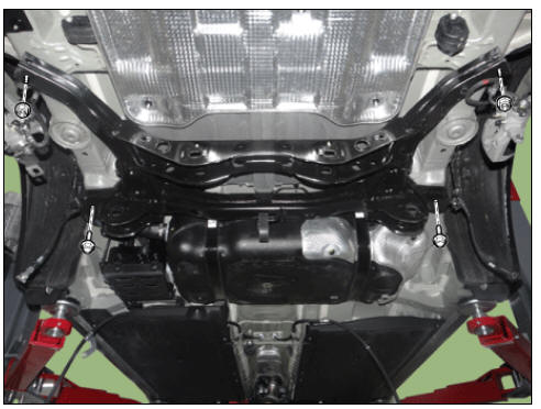
- Loosen the bolts and nuts and then remove the rear cross member.
Tightening torque: 156.9 - 176.5 N*m (16.0 - 18.0 kgf*m, 115.7 - 130.2 lb*ft)
- Install in the reverse order of removal.
- Check the wheel alignment.
(Refer to Suspension System - "Alignment")
READ NEXT:
 Tire Repair procedures
Warning
Using tires and wheel other than the recommended sizes could cause
unusual handling characteristics
and poor vehicle control, resulting in a serious accident.
Measure the tread depth of the tires.
Tread depth (limit) : 1.6 mm (0.06
Alignment Repair procedures
Front wheel alignment
Warning
When using a commercially available computerized wheel alignment
equipment to inspect the front wheel
alignment, always position the vehicle on a level surface with the front wheels
facing straight ahead.
Prior
SEE MORE:
Rear Door Module
Rear door module
Replacement
Remove the rear door window glass.
(Refer to Rear Door - "Rear Door Window Glass")
Remove the rear door channel (A) after loosening the mounting bolts and
nut.
Tightening torque :
Bolt :
Towing service
Wheel dolly
Proper lifting and towing procedures
are necessary to prevent damage to
the vehicle. The use of wheel dolly (1)
or flatbed is recommended.
On 2WD vehicles, it is acceptable to
tow the vehicle with the rear wheels
Categories
- Home
- KIA Niro EV, Hybrid - Second generation - (SG2) (2021-2024) - Owner's manual
- Kia Niro - First generation - (DE) (2017-2022) - Service and Repair Manual
- Contact Us