KIA Niro: The Power Relay Assembly
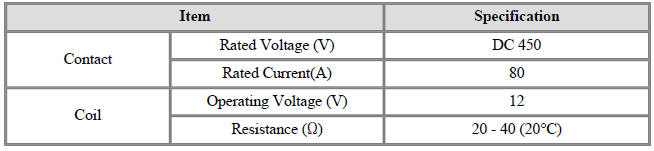
Specification
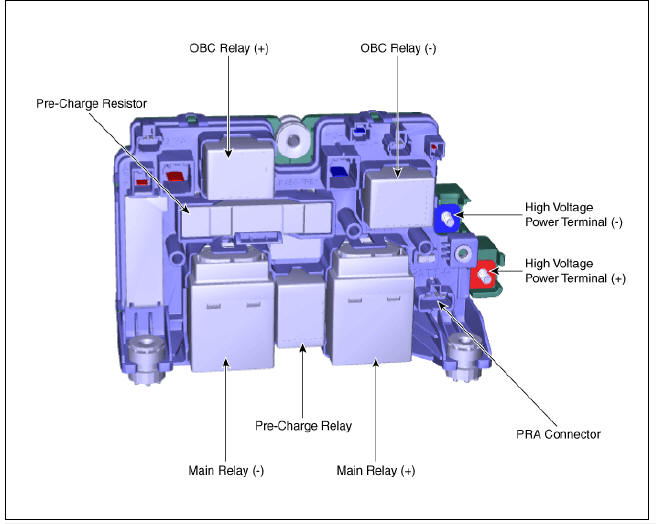
Description
The Power Relay Assembly (PRA) consists of the positive and negative main relays, pre-charge relay, pre-charge resistor and battery current sensor. It is located inside the battery pack assembly and controls the high voltage power circuit between the high voltage battery and inverter by the control signal of BMS ECU.
PRA Operation Sequence
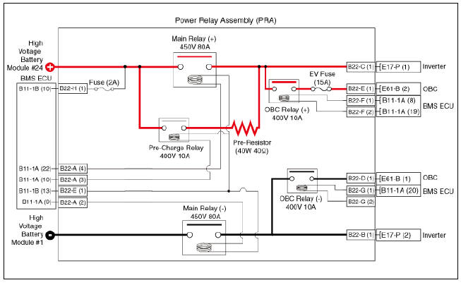
Circuit Diagram
Removal
Warning
- Be sure to read and follow the "General Safety Information and Caution" before doing any work related with the high voltage system. Failure to follow the safety instructions may result in serious electrical injuries.
- Be sure to read and follow the "High Voltage Shut-off Procedures" before doing any work related with the high voltage system. Failure to follow the safety instructions may result in serious electrical injuries.
- Turn ignition switch OFF and disconnect the negative (-) battery cable.
- Shut off the high voltage circuit.
(Refer to Hybrid Control System - "High Voltage Shut-off Procedures")
- Remove the power relay assembly.
(Refer to High Voltage Battery System - "Power Relay Assembly")
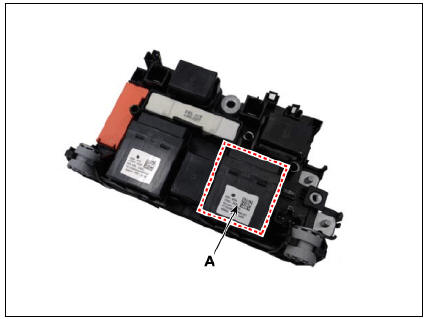
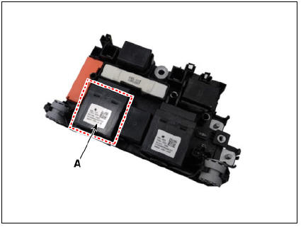
- Remove the main relay (A).
Main Relay (+)
Main Relay (-)
Installation
Warning
- Be sure to read and follow the "General Safety Information and Caution" before doing any work related with the high voltage system. Failure to follow the safety instructions may result in serious electrical injuries.
- Be sure to read and follow the "High Voltage Shut-off Procedures" before doing any work related with the high voltage system. Failure to follow the safety instructions may result in serious electrical injuries.
- Install the main relay in the reverse order of removal.
Inspection
Warning
- Be sure to read and follow the "General Safety Information and Caution" before doing any work related with the high voltage system. Failure to follow the safety instructions may result in serious electrical injuries.
- Be sure to read and follow the "High Voltage Shut-off Procedures" before doing any work related with the high voltage system. Failure to follow the safety instructions may result in serious electrical injuries.
Checking for Welding in the High Voltage Main Relay
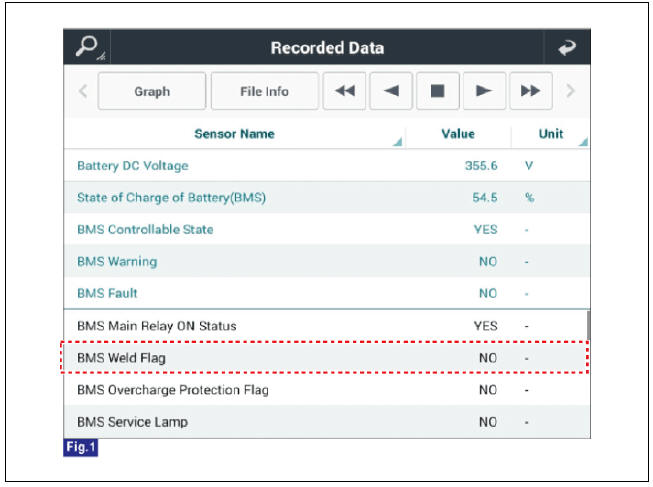
Using KDS service data to check for main relay weld damage
- Connect the KDS to the Data Link Connector (DLC).
- Turn the ignition switch ON.
- Check the BMS weld damage state in the KDS service data.
Using a Multimeter to measure weld damage
- Shut off the high voltage.
(Refer to "High Voltage Shut-off Procedures")
- Remove the high voltage battery rear cover.
(Refer to "High Voltage Battery System - "Case")
- Remove the inlet cooling duct.
(Refer to Hybrid Control System - "Cooling Duct")
- Measure the high voltage main relay resistance and check for signs of weld damage.
Specification : ¥Ω (20ºC (68ºF))
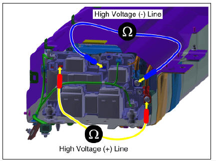
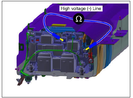
High voltage main relay (-) switch resistance
- Shut off the high voltage.
(Refer to "High Voltage Shut-off Procedures")
- Remove the high voltage battery rear cover.
(Refer to "High Voltage Battery System - "Case")
- Remove the inlet cooling duct.
(Refer to Hybrid Control System - "Cooling Duct")
- Measure the resistance between the high voltage power terminal (-) and the inverter power terminal (-).
Circuit inspection (Relay ON)
Warning
Inspect the high voltage main relay (-) activated by KDS.
- Connect the KDS to the Data Link Connector (DLC).
- Turn the ignition switch ON.
- Activate the main relay by using "Actuation Test" on the KDS as shown in the illustration below.
Warning
When the relay is ON, there is a relay operation sound.
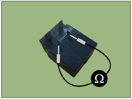
High Voltage Main Relay Coil Resistance
- Shut off the high voltage.
(Refer to "High Voltage Shut-off Procedures")
- Remove the power relay assembly.
(High Battery System - "Power Relay Assembly")
- Check for continuity between the terminals using an ohmmeter.
READ NEXT:
 Pre-Charge Relay
Specification
Description
The Power Relay Assembly (PRA) consists of the positive and negative main
relays, pre-charge relay, pre-charge resistor and
battery current sensor. It is located inside the battery pack assembly and
controls the h
Pre-Charge Resistor
Specification
Description
Pre-Charge Resistor is integrated into the Power Relay Assembly (PRA). It
protects the high voltage circuit by limiting the
current while the inverter capacitor is being charged.
PRA Operation Sequence
Cir
Battery Current Sensor
Specification
Battery Current Sensor
Specification
Description
Battery Current Sensor is integrated into the Power Relay Assembly (PRA) and
measures the current
of the high voltage battery during charging or discharging.
Installation
SEE MORE:
Door locks outside the vehicle
Locking/unlocking with the smart key
Operation
Press the front door handle button
(driver's side).
Hazard warning lights will blink and
the chime will sound.
Locking: Once
Unlocking: Twice
Operating condition(s)
All
Front Wiper Motor
Front wiper motor
Rear wiper motor
Front Wiper Motor Repair procedures
Removal
Front Wiper Motor
Remove the cowl top cover.
(Refer to Body - "Cowl Top Cover")
Disconnect the wiper motor connector (A).
Remove th
Categories
- Home
- KIA Niro EV, Hybrid - Second generation - (SG2) (2021-2024) - Owner's manual
- Kia Niro - First generation - (DE) (2017-2022) - Service and Repair Manual
- Contact Us