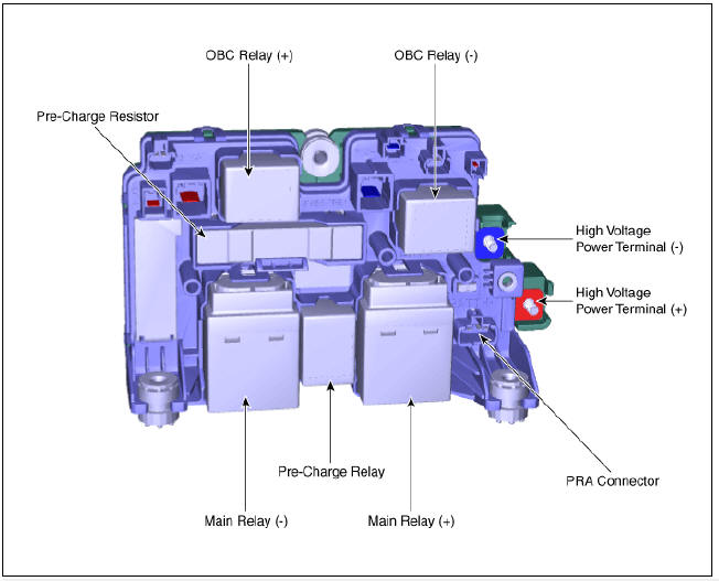
KIA Niro: Pre-Charge Resistor
Specification

Description
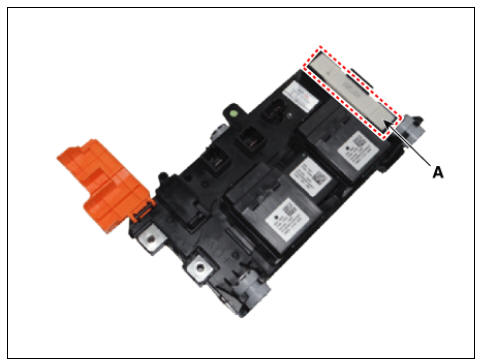
Pre-Charge Resistor is integrated into the Power Relay Assembly (PRA). It protects the high voltage circuit by limiting the current while the inverter capacitor is being charged.
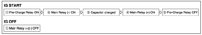
PRA Operation Sequence
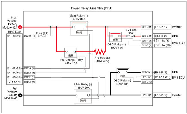
Circuit Diagram
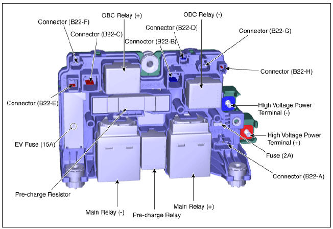
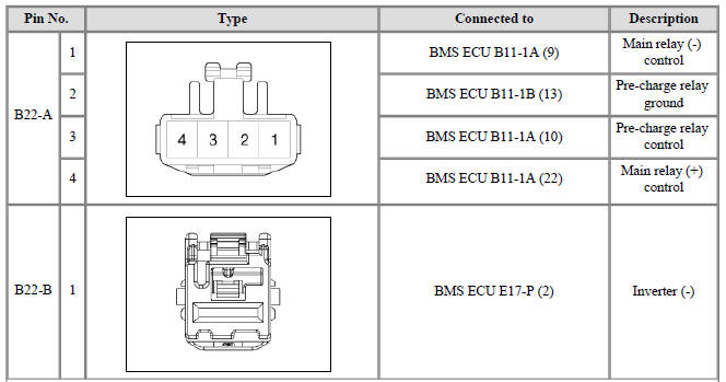
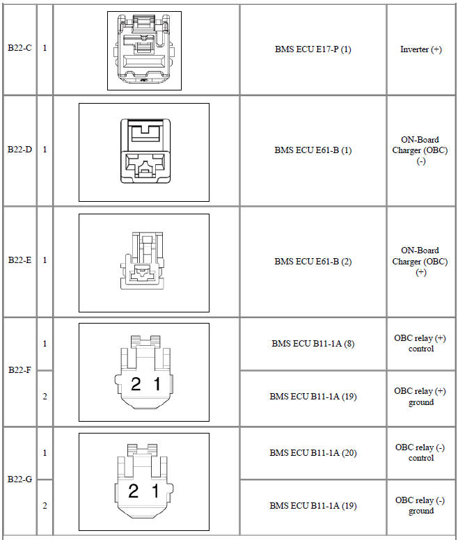
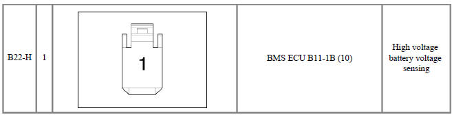
Harness Connector and Terminal Function
Pre-Charge Resistor Repair procedures
Warning
- Be sure to read and follow the "General Safety Information and Caution" before doing any work related with the high voltage system. Failure to follow the safety instructions may result in serious electrical injuries.
- Be sure to read and follow the "High Voltage Shut-off Procedures" before doing any work related with the high voltage system. Failure to follow the safety instructions may result in serious electrical injuries.
- Switch "OFF" the ignition and disconnect the negative (-) terminal of the auxiliary 12V battery.
- Shut off the high voltage circuit.
(Refer to Hybrid Control System - "High Voltage Shut-off Procedures")
- Remove the power relay assembly.
(Refer to High Voltage Battery System - "Power Relay Assembly")
- Insert a screwdriver or an awl (B) into the hole (A).
- Lift the pre-charge resistor (D) in the direction of arrow (C).
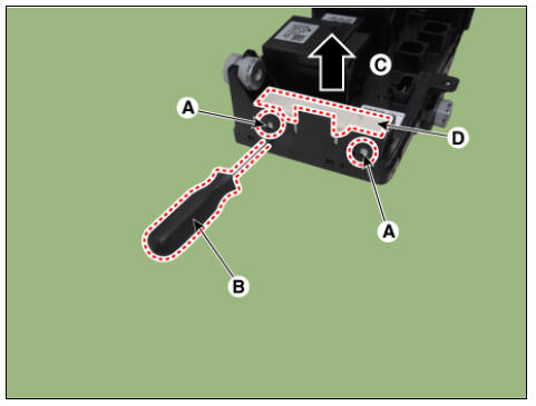
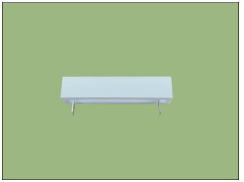
- Remove the pre-charge resistor (A).
Installation
Warning
- Be sure to read and follow the "General Safety Information and
Caution" before doing any work related
with the high voltage system. Failure to follow the safety instructions may
result in serious electrical
injuries.
- Be sure to read and follow the "High Voltage Shut-off Procedures" before doing any work related with the high voltage system. Failure to follow the safety instructions may result in serious electrical injuries.
- Install in the reverse order of removal.
Inspection
Warning
- Be sure to read and follow the "General Safety Information and Caution" before doing any work related with the high voltage system. Failure to follow the safety instructions may result in serious electrical injuries.
- Be sure to read and follow the "High Voltage Shut-off Procedures" before doing any work related with the high voltage system. Failure to follow the safety instructions may result in serious electrical injuries.
- Remove the pre-charge resistor.
(Refer to High Voltage Battery Control System - "Pre-Charge Resistor")
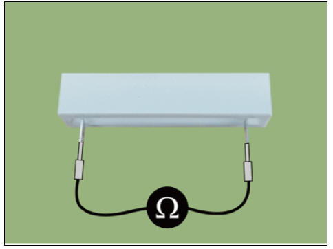
- Check for continuity between the terminals using an ohmmeter.
Specification : 40Ω (20ºC (68ºF))
READ NEXT:
 Battery Current Sensor
Specification
Battery Current Sensor
Specification
Description
Battery Current Sensor is integrated into the Power Relay Assembly (PRA) and
measures the current
of the high voltage battery during charging or discharging.
Installation
Battery Temperature Sensor
Specification
Air Inlet Temperature Sensor
Battery Temperature Sensor (Side of cell)
Description
Battery Temperature Sensor is installed inside the high voltage battery pack
assembly. It measures the temperature of t
Cell Monitoring Unit (CMU) Terminal And Input/Output
Signal
System Configuration
Connector Type
Terminal Function
Cell Monitoring Unit (CMU) #1 (Sub Voltage Battery Pack Assembly)
Connector (B01-A) (16Pin) : High Voltage Battery control
Connector (B01-C) (12Pin) : High Voltage Battery Cel
SEE MORE:
Crankshaft Bore Identification Mark
Letters are been stamped on the block as a mark for the size of each of the 5
main journal bores.
Use them, and the numbers or bar stamped on the crank (marks for main journal
size), to choose the correct
bearings.
Cylinder Block Specifi
Cylinder Head Repair procedures
Removal
Engine removal is not required for this procedure.
Warning
Be sure to read and follow the "General Safety Information and
Caution" before doing any work related
with the high voltage system. Failure to follow the safety instruction
Categories
- Home
- KIA Niro EV, Hybrid - Second generation - (SG2) (2021-2024) - Owner's manual
- Kia Niro - First generation - (DE) (2017-2022) - Service and Repair Manual
- Contact Us