KIA Niro: Battery Temperature Sensor
Specification
Air Inlet Temperature Sensor
Battery Temperature Sensor (Side of cell)

Description
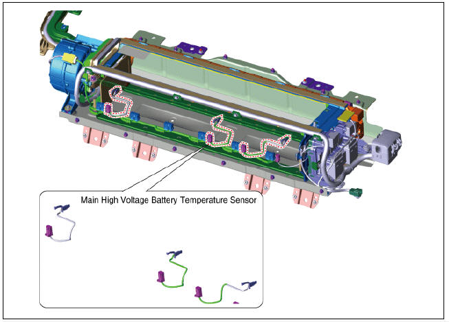
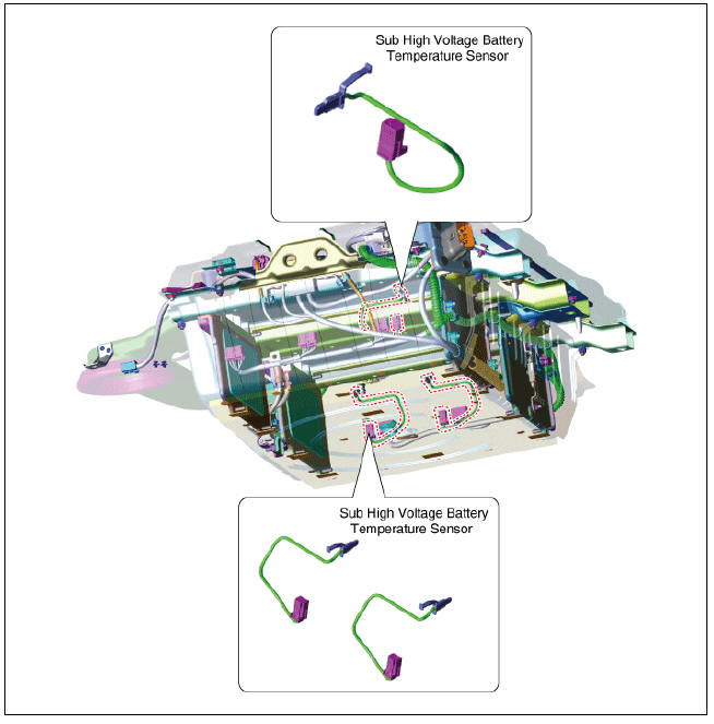
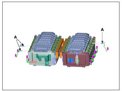
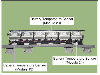
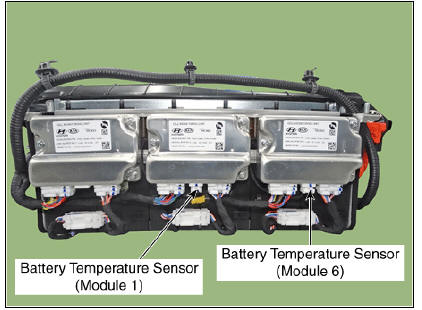
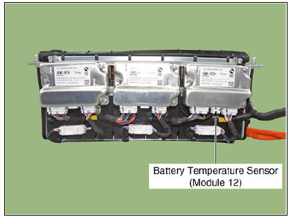
Battery Temperature Sensor is installed inside the high voltage battery pack assembly. It measures the temperature of the battery module 13, 20, 24 and air inlet sub high voltage battery module 1, 6, 12. In addition, it integrates the voltage sensing wiring for each module.
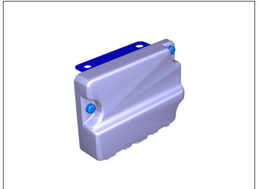
Main High Voltage Battery Temperature Sensor
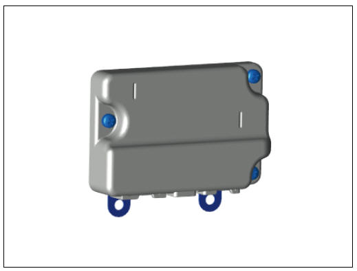
Sub High Voltage Battery Temperature Sensor
Circuit Diagram

Main High Voltage Battery Temperature Sensor
Removal
Warning
- Be sure to read and follow the "General Safety Information and Caution" before doing any work related with the high voltage system. Failure to follow the safety instructions may result in serious electrical injuries.
- Be sure to read and follow the "High Voltage Shut-off Procedures" before doing any work related with the high voltage system. Failure to follow the safety instructions may result in serious electrical injuries.
Main High Voltage Battery Temperature Sensor
- Switch "OFF" the ignition and disconnect the negative (-) terminal of the auxiliary 12V battery.
- Shut off the high voltage circuit.
(Refer to Hybrid Control System - "High Voltage Shutoff Procedure")
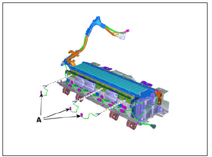
- Remove the main high voltage battery system assembly.
(Refer to High Voltage Battery System - "Removal")
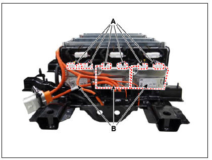
- Disconnect the cell monitoring unit connector (A).
- Remove the cell monitoring unit (B) after loosening the mounting nut and screw.
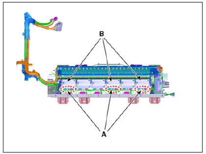
- Remove the battery temperature sensor (A).
Sub High Voltage Battery Temperature Sensor
- Switch "OFF" the ignition and disconnect the negative (-) terminal of the auxiliary 12V battery.
- Shut off the high voltage circuit.
(Refer to Hybrid Control System - "High Voltage Shutoff Procedure")
- Remove the sub high voltage battery system assembly.
(Refer to High Voltage Battery System - "Removal")
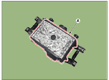
- Remove the high voltage battery watertight case (A).
- Disconnect the cell monitoring unit connector (A).
- Remove the cell monitoring unit (B) after loosening the mounting screw.
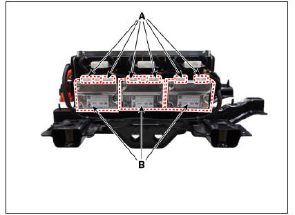
- Remove the battery temperature sensor (A).
Installation
Warning
- Be sure to read and follow the "General Safety Information and Caution" before doing any work related with the high voltage system. Failure to follow the safety instructions may result in serious electrical injuries.
- Be sure to read and follow the "High Voltage Shut-off Procedures" before doing any work related with the high voltage system. Failure to follow the safety instructions may result in serious electrical injuries.
- Install the battery temperature sensors in the reverse order of removal.
Inspection
Warning
- Be sure to read and follow the "General Safety Information and Caution" before doing any work related with the high voltage system. Failure to follow the safety instructions may result in serious electrical injuries.
- Be sure to read and follow the "High Voltage Shut-off Procedures" before doing any work related with the high voltage system. Failure to follow the safety instructions may result in serious electrical injuries.
- Shut off the high voltage circuit.
(Refer to "High Voltage Shutoff Procedure")
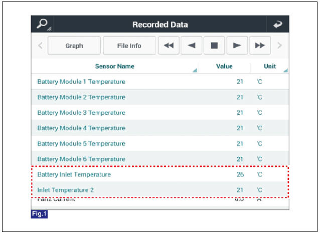
- Connect the KDS to the Data Link Connector (DLC).
- Turn the ignition switch ON.
- Check the battery temperature in KDS service data.
- Disconnect the battery temperature signal connector (A).
Main High Voltage Battery Temperature Sensor
Sub High Voltage Battery Temperature Sensor
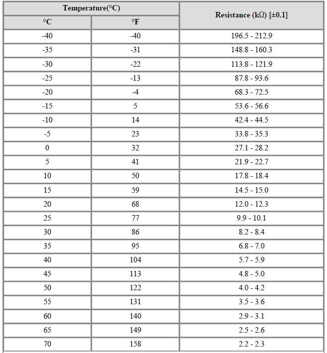
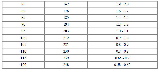
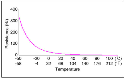
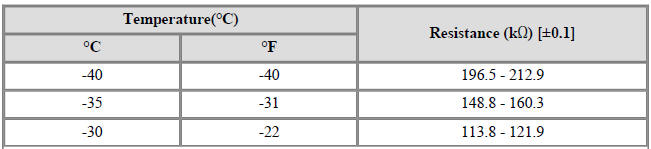
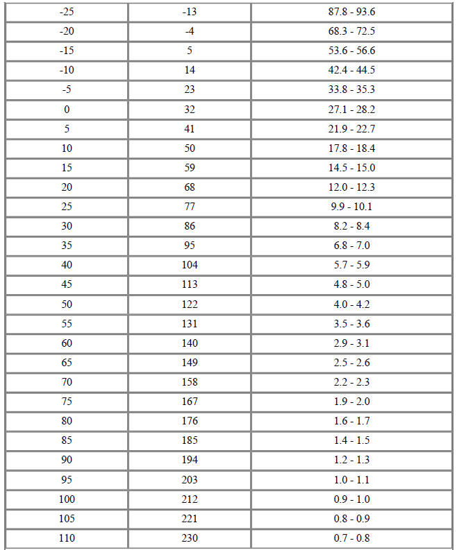
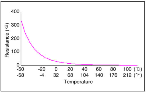
- Measure resistances of the temperature signal terminals (Refer to the table below), then compare the value with the KDS service data.
Specification : Refer to "Specification"
Description
The cell monitoring unit (CMU) is attached to the side of each high voltage
battery module. It
measures the temperature, voltage, VDP of each high voltage battery module and
sends the data to
BMS ECU.
Main High voltage Battery Side
Sub High voltage Battery Side
READ NEXT:
 Cell Monitoring Unit (CMU) Terminal And Input/Output
Signal
Cell Monitoring Unit (CMU) Terminal And Input/Output
Signal
System Configuration
Connector Type
Terminal Function
Cell Monitoring Unit (CMU) #1 (Sub Voltage Battery Pack Assembly)
Connector (B01-A) (16Pin) : High Voltage Battery control
Connector (B01-C) (12Pin) : High Voltage Battery Cel
Sub High Voltage Battery
Removal
Warning
Be sure to read and follow the "General Safety Information and
Caution" before doing any work
related with the high voltage system. Failure to follow the safety
instructions may result in
serious electrical in
Main High Voltage Battery Temperature Sensor
Removal
Warning
Be sure to read and follow the "General Safety Information and
Caution" before doing any work
related with the high voltage system. Failure to follow the safety
instructions may result in
serious electrical in
SEE MORE:
Oil Level Check
Remove the under cover.
(Refer to Engine Mechanical System - "Engine Room Under Cover")
Remove the oil filler plug (A or B).
Check the condition of the oil and make sure that it is at the proper
level (A).
Inst
Seat warmer/ventilation
The seat warmer/ventilation is provided
to warm/cool the front and the rear
seats.
* The seat ventilation is provided only on
the front seats.
Operation
Push the button to control the function.
It defaults to the OFF position the
veh
Categories
- Home
- KIA Niro EV, Hybrid - Second generation - (SG2) (2021-2024) - Owner's manual
- Kia Niro - First generation - (DE) (2017-2022) - Service and Repair Manual
- Contact Us