KIA Niro: Battery Current Sensor
Specification
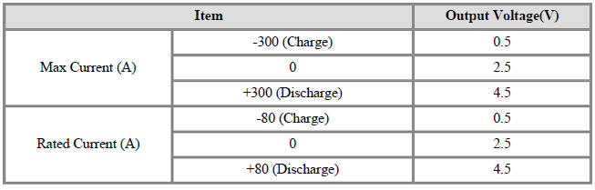
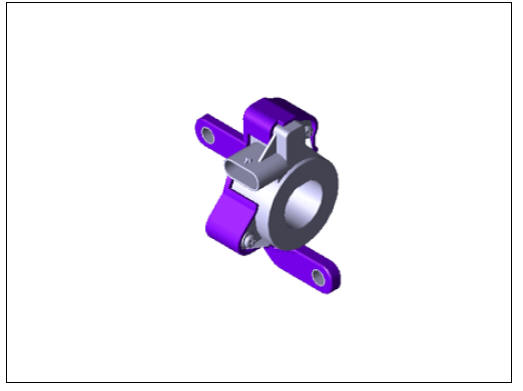
Battery Current Sensor
Specification
Description
Battery Current Sensor is integrated into the Power Relay Assembly (PRA) and
measures the current
of the high voltage battery during charging or discharging.
Installation
Warning
- Be sure to read and follow the "General Safety Information and Caution" before doing any work related with the high voltage system. Failure to follow the safety instructions may result in serious electrical injuries.
- Be sure to read and follow the "High Voltage Shut-off Procedures" before doing any work related with the high voltage system. Failure to follow the safety instructions may result in serious electrical injuries.
- Install in the reverse order of removal.
Inspection
Warning
- Be sure to read and follow the "General Safety Information and Caution" before doing any work related with the high voltage system. Failure to follow the safety instructions may result in serious electrical injuries.
- Be sure to read and follow the "High Voltage Shut-off Procedures" before doing any work related with the high voltage system. Failure to follow the safety instructions may result in serious electrical injuries.
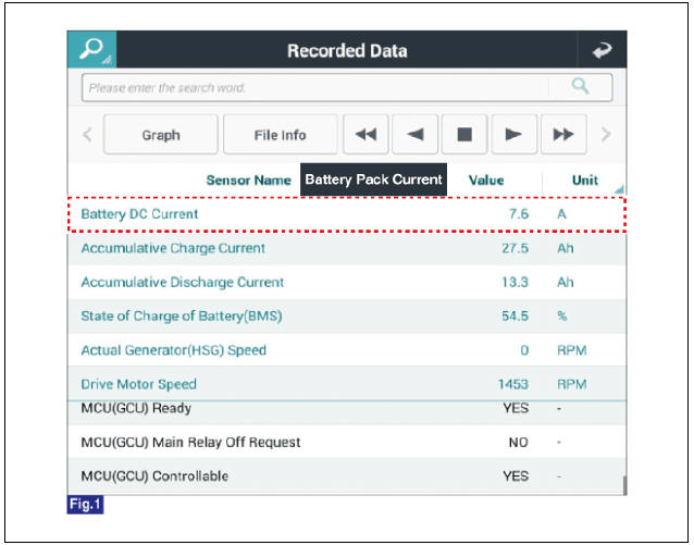
- Connect the KDS to the Data Link Connector (DLC).
- Turn the ignition switch ON.
- Check the battery current in KDS service data.
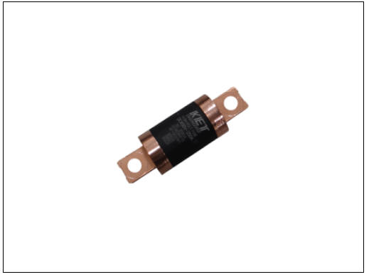
Main Fuse
Specification
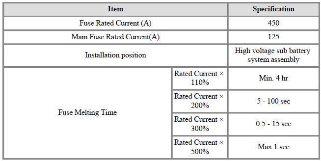
Description
The main fuse is mounted in the safety plug and protects the high voltage battery and high voltage circuits from overcurrent.
Main Fuse Repair procedures
Removal
Warning
- Be sure to read and follow the "General Safety Information and Caution" before doing any work related with the high voltage system. Failure to follow the safety instructions may result in serious electrical injuries.
- Be sure to read and follow the "High Voltage Shut-off Procedures" before doing any work related with the high voltage system. Failure to follow the safety instructions may result in serious electrical injuries
- Turn the ignition switch OFF and disconnect the auxiliary 12V battery negative (-) terminal.
- Shut off the high voltage circuit.
(Refer to Hybrid Control System - "High Voltage Shutoff Procedure")
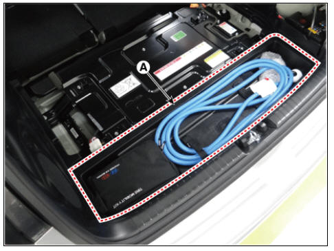
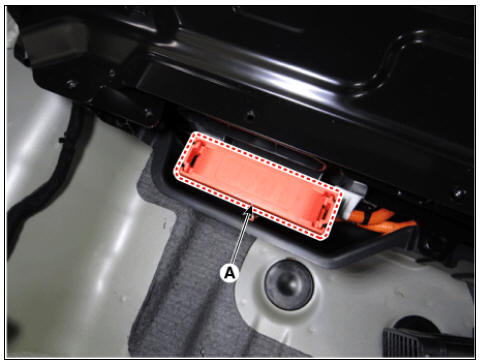
- Remove the center tray trim (A)
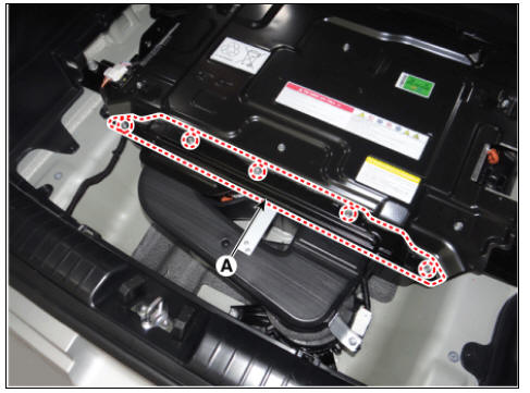
- Remove the sub high voltage battery rear cover (A) after loosening the mounting bolts.
High Voltage Battery Rear Cover mounting bolt : 7.8 - 11.8 N*m (0.8 - 1.2 kgf*m, 5.8 - 8.7 lb*ft)
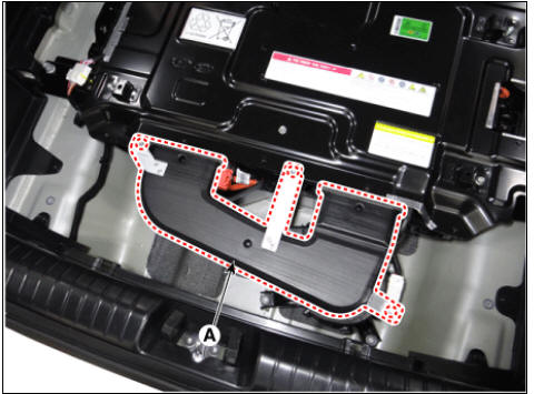
- Remove the rear outlet cooling duct (A) after loosening the mounting bolt.
Rear Outlet Cooling Duct mounting bolt : 7.8 - 11.8 N*m (0.8 - 1.2 kgf*m, 5.8 - 8.7 lb*ft)
- Remove the main fuse cover (A).
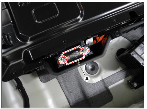
- Remove the main fuse (A) after loosening the mountiong nuts.
Main Fuse mounting nut : 10.98 - 12.94 N*m (1.12 ~ 1.32 kgf*m, 8.10 - 9.55 lb*ft)
Installation
Warning
- Be sure to read and follow the "General Safety Information and Caution" before doing any work related with the high voltage system. Failure to follow the safety instructions may result in serious electrical injuries.
- Be sure to read and follow the "High Voltage Shut-off Procedures" before doing any work related with the high voltage system. Failure to follow the safety instructions may result in serious electrical injuries.
- Install the main fuse in the reverse order of removal.
Warning
Be careful not to miss washers when installing the main fuse.
Inspection
Warning
- Be sure to read and follow the "General Safety Information and Caution" before doing any work related with the high voltage system. Failure to follow the safety instructions may result in serious electrical injuries.
- Be sure to read and follow the "High Voltage Shut-off Procedures" before doing any work related with the high voltage system. Failure to follow the safety instructions may result in serious electrical injuries.
- Remove the main fuse.
(Refer to High Voltage Battery Control System - "Main Fuse")
- Check the continuity between ends of the main fuse.
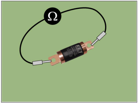
Specification : 1Ω or less (20ºC (68ºF))
- If the measured resistance is not within the spec value, then exchange the main fuse by following the maintenance guideline.
READ NEXT:
 Battery Temperature Sensor
Specification
Air Inlet Temperature Sensor
Battery Temperature Sensor (Side of cell)
Description
Battery Temperature Sensor is installed inside the high voltage battery pack
assembly. It measures the temperature of t
Cell Monitoring Unit (CMU) Terminal And Input/Output
Signal
System Configuration
Connector Type
Terminal Function
Cell Monitoring Unit (CMU) #1 (Sub Voltage Battery Pack Assembly)
Connector (B01-A) (16Pin) : High Voltage Battery control
Connector (B01-C) (12Pin) : High Voltage Battery Cel
Sub High Voltage Battery
Removal
Warning
Be sure to read and follow the "General Safety Information and
Caution" before doing any work
related with the high voltage system. Failure to follow the safety
instructions may result in
serious electrical in
SEE MORE:
Rear Door Belt Outside/ Inside Weatherstrip
Rear Door Belt Outside Weatherstrip
Replacement
Pull down the rear door window glass to the lowest level by pressing the
power window glass
switch.
Remove the rear door belt outside weatherstrip (A) after loosening the
mounting screw.
Sunroof
Sunroof / Components And Components Location
Sunroof
Sunroof switch
Sunroof motor & controller
Description
The Sunroof is quiped with a one touch on/off switch to open and close the
glass, and it has an ANTIPINCH
function which
Categories
- Home
- KIA Niro EV, Hybrid - Second generation - (SG2) (2021-2024) - Owner's manual
- Kia Niro - First generation - (DE) (2017-2022) - Service and Repair Manual
- Contact Us