KIA Niro: Driveshaft Assembly
Removal
The type can replace the wheel side joint boot
- Remove the front driveshaft.
(Refer to Driveshaft Assembly - "Front driveshaft")
- Remove the transaxle side joint.
(Refer to Driveshaft Assembly - "Joint Assembly(Transaxle side)")
- Remove the dynamic damper. (If equipped) (Refer to Driveshaft Assembly - "Dynamic Damper")
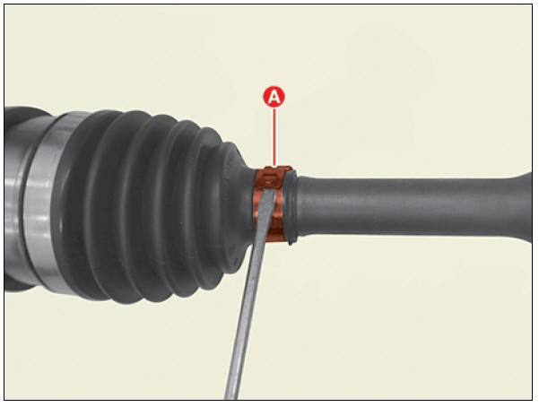
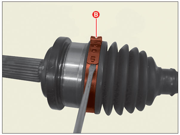
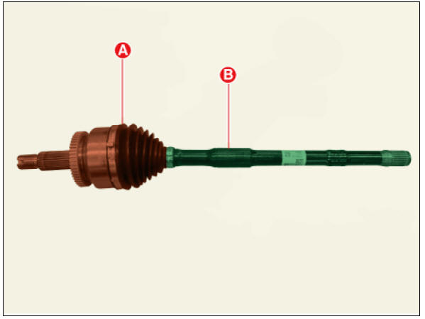
- Remove the wheel side joint small diameter (A) and large diameter (B) boot band using driver (-).
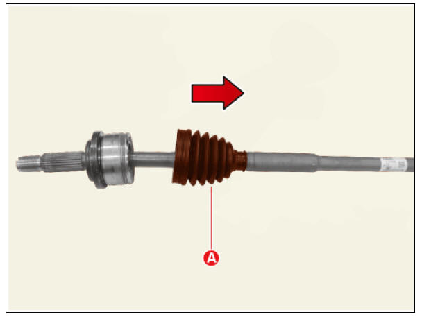
- Remove the wheel side joint boot (A).
Warning
- Do not remove the wheel side joint housing (A).
- Reinstall the wheel side joint housing (A) may cause leakage,
so replace it with the shaft (B) as an
assembly.
The type can not replace the wheel side joint boot
- Remove the front driveshaft.
(Refer to Driveshaft Assembly - "Front driveshaft")
- Remove the transaxle side joint.
(Refer to Driveshaft Assembly - "Joint Assembly(Transaxle side)")
- Remove the dynamic damper. (if equipped) (Refer to Driveshaft Assembly - "Dynamic Damper")
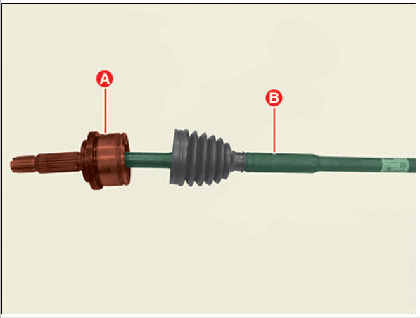
- Replace the wheel side joint assembly (A) and shaft (B).
Warning
The wheel side joint boot can not be replaced, so replace the wheel side joint assembly (A) and shaft (B) together as an assembly.
Inspection
- Check the boot for water or foreign objects.
- Replace any defective parts.
Installation
The type can replace the wheel side joint boot
Warning
- When assembling, be careful not to let dust and foreign substances enter.
- Driveshaft joints require special grease, so do not add any other type of grease.
- Boot bands must use the new one.
- Install the new boot (A) in the direction of the arrow.
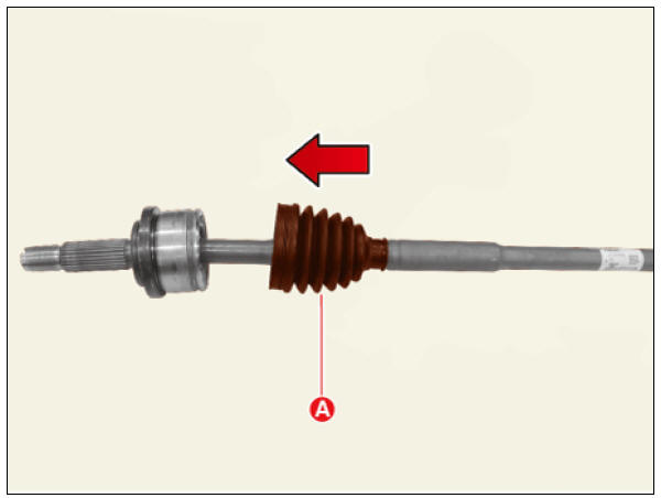
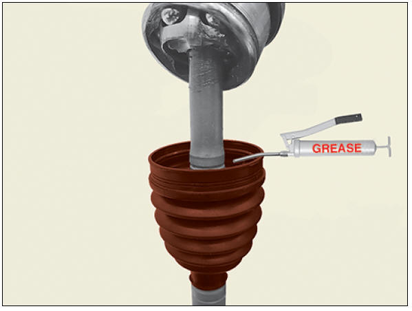
- Apply the grease specified inside the boot.
Warning
- Use the grease provided with the joint/boot kit.
- Apply about 50 - 60% grease inside the boot.
- Driveshaft joints require special grease, so do not add any other type of grease.
- Install the wheel side boot (A) into the housing (B).
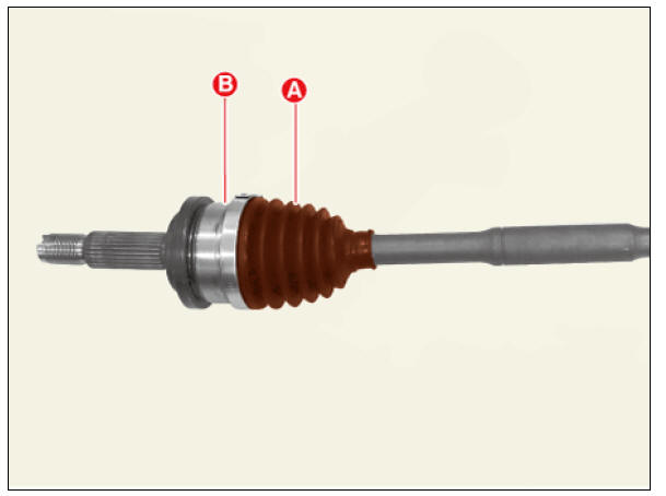
- Install the large diameter boot band using SST (0K495-C5000).
Clearance (A) : 2.0 mm or less.
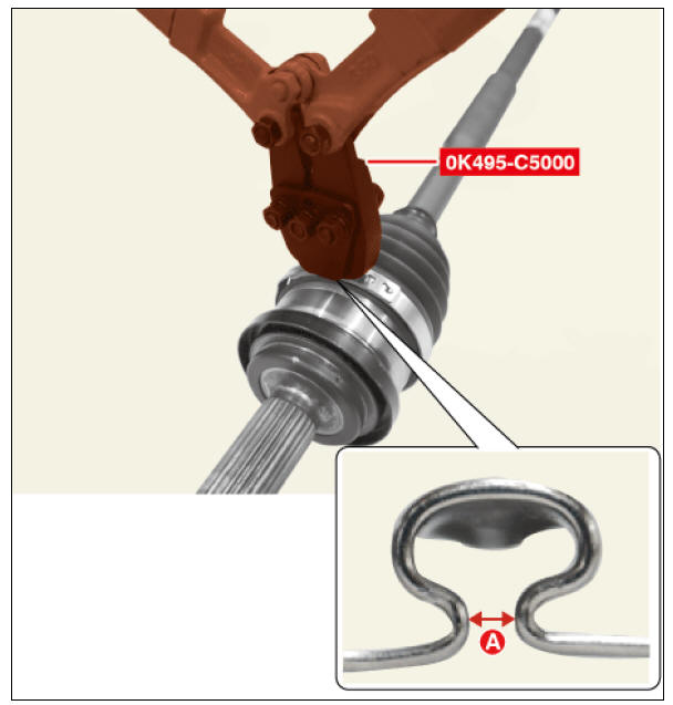
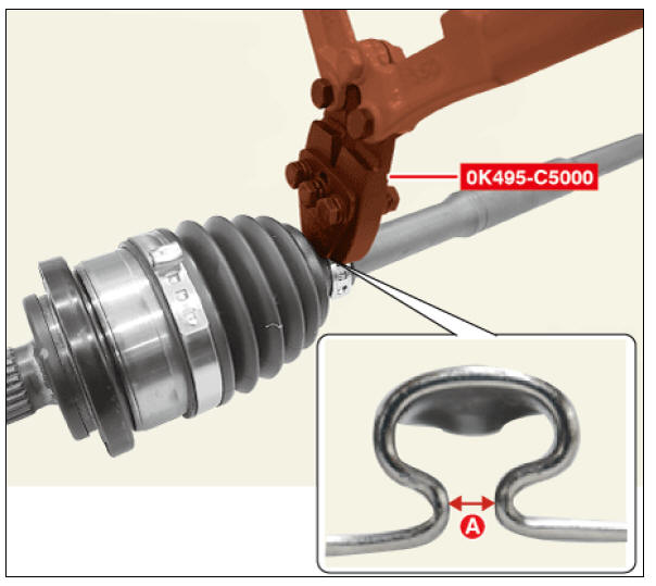
- Install the small diameter boot band using SST (0K495-C5000).
Clearance (A) : 2.0 mm or less.
Warning
When installing the boot band, align the fastened direction with the
wheel side joint large diameter boot
band. 
- Install the dynamic damper . (If equipped) (Refer to Driveshaft Assembly - "Dynamic Damper")
- Install the transaxle side joint.
(Refer to Driveshaft Assembly - "Joint Assembly(Transaxle side)")
- Install the front drive shaft.
(Refer to Driveshaft Assembly - "Front Driveshaft")
The type can not replace the wheel side joint boot
Warning
- When assembling, be careful not to let dust and foreign substances enter.
- Driveshaft joints require special grease, so do not add any other type of grease.
- Boot bands must use the new one.
- Replace the wheel side joint assembly (A) and shaft (B).
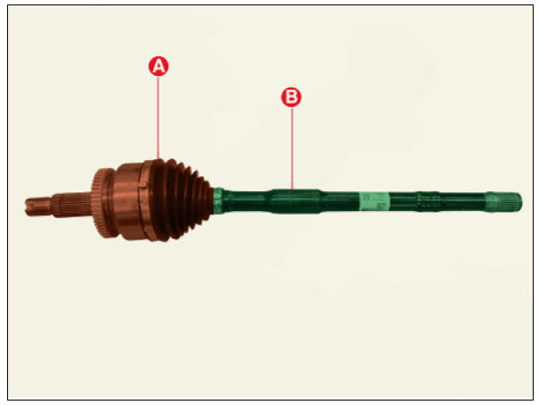
Warning
The wheel side joint boot can not be replaced, so replace the wheel side joint assembly (A) and shaft (B) together as an assembly.
- Install the Dynamic damper. (If equipped) (Refer to Driveshaft Assembly - "Dynamic Damper")
- Install the transaxle side joint.
(Refer to Driveshaft Assembly - "Joint Assembly(Transaxle side)")
- Install the front drive shaft.
(Refer to Driveshaft Assembly - "Front Driveshaft")
READ NEXT:
 Front Hub / Knuckle
Components
Brake disc
Hub assembly
Dust cover
Knuckle
Front Hub / Knuckle / Repair Procedures
Removal
Remove the wheel and tire.
Tightening torque :
107.9 - 127.5 N*m (11.0 - 13.0 kgf*m, 79.6 - 94.0 lb*ft)
Warning
Be c
Rear Axle Assembly / Rear Hub - Carrier
Components
Disc
Dust cover
Rear hub
Rear Knuckle
Rear Hub - Carrier / Repair Procedures
Removal
Remove the tire (A).
Tightening torque :
107.9 - 127.5 N*m (11.0 - 13.0 kgf*m, 79.6 - 94.0 lb*ft)
Warning
Be careful not t
Suspension System
Service
Data
Front Suspension
Rear Suspension
Wheel & Tire
Wheel Alignment
Tightening
Torques
Front Suspension
Rear Suspension
Special Service Tools
Tool Name / Number / IIIustration
/ Description
SEE MORE:
Inhibitor Switch Repair procedures
Inspection
Warning
Inspect the following items by referring to inspection flow chart.
(Refer to Inhibitor Switch - "Troubleshooting")
Check the diagnostic trouble codes (DTC) using KDS.
Inspect if "N" range setting matc
Good driving practices
Never change the gear from P (Park)
or N (Neutral) to any other position
with the accelerator pedal depressed.
Never change the gear into P (Park)
when the vehicle is moving.
Stop the vehicle completely before
changing the gear into R
Categories
- Home
- KIA Niro EV, Hybrid - Second generation - (SG2) (2021-2024) - Owner's manual
- Kia Niro - First generation - (DE) (2017-2022) - Service and Repair Manual
- Contact Us