KIA Niro: Front Driveshaft Repair procedures
Component location
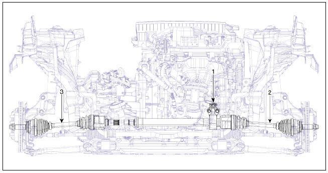
- Inner shaft bearing bracket
- Drive shaft (RH)
- Drive shasft (LH)
Front Driveshaft Repair procedures
Removal
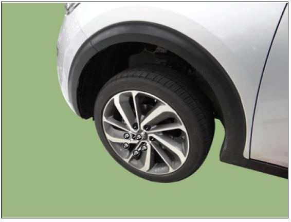
- Remove the wheel and tire.
Tightening torque: 107.9 - 127.5 N*m (11.0 - 13.0 kgf*m, 79.6 - 94.0 lb*ft)
Warning
Be careful not to damage the wheel nuts when removing the wheel and tire.
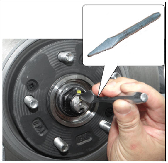
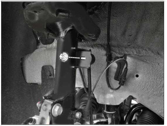
- By hammering on a chisel, unlock the driveshaft lock hub nut caulking.
Warning
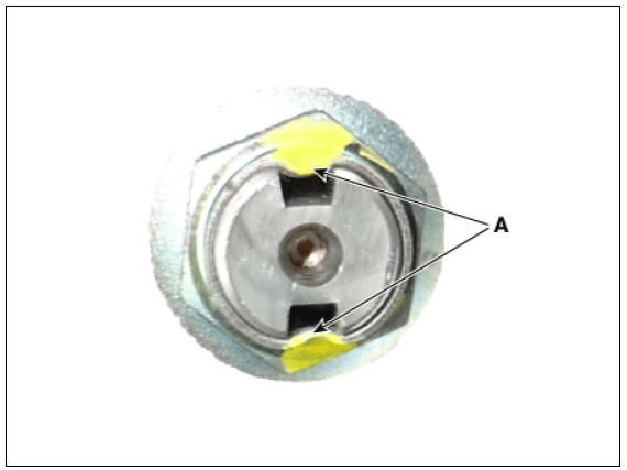
If there is screw thread (A) on the end of the nut, unlock the
caulking by using a chisel and then loosen the nut
to prevent damaging driveshaft screw thread.
- Remove the caulking nut (A) from the front axle.
Tightening torque: 274.6 - 294.2 N*m (28.0 - 30.0 kgf*m, 202.5 - 217.0 lb*ft)

Warning
The driveshaft lock nut must be replaced with new one. When
replacing the drive lock hub nut, use only the
nut with screw thread (A) on the end 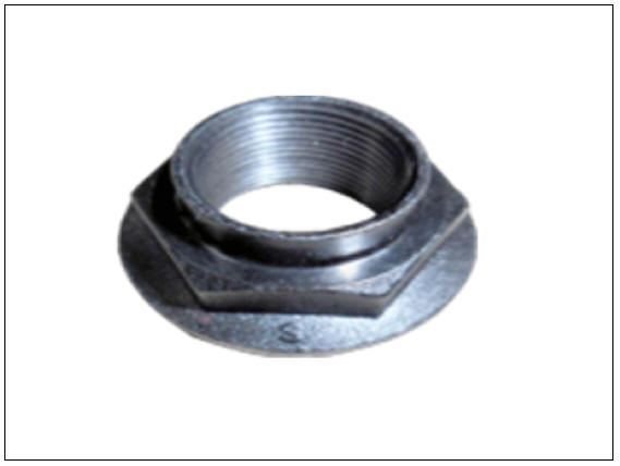

- Tighten the driveshaft lock hub nut to the specified tightening torque, and caulk by using a chisel and hammer.
- If there are two key seats, perform on all two seats.
Caulking depth (A) : 1.5 mm (0.0591 in)
- Remove the under cover.
(Refer to Engine Mechanical System - "Engine Room Under Cover")
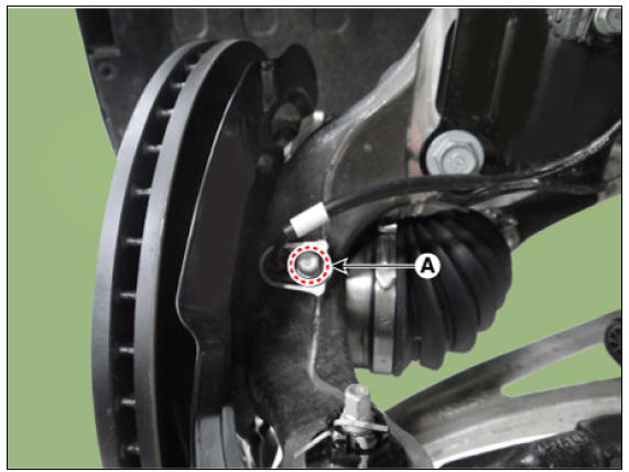
- Remove the wheel speed sensor bolt (A).
Tightening torque : 6.8 - 10.7 N*m (0.7 - 1.1 kgf*m, 5.0 - 7.9 lb*ft)
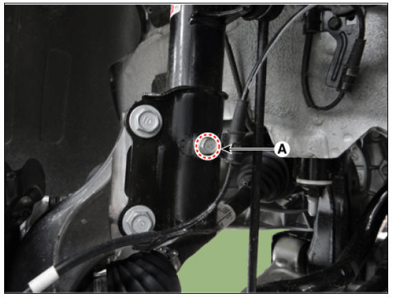
- Remove the wheel speed sensor bracket bolt (A).
Tightening torque : 8.8 - 13.7 N*m (0.9 - 1.4 kgf*m, 6.5 - 10.1 lb*ft)
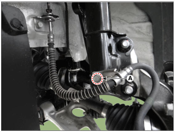
- Remove the caliper hose bracket bolt (A).
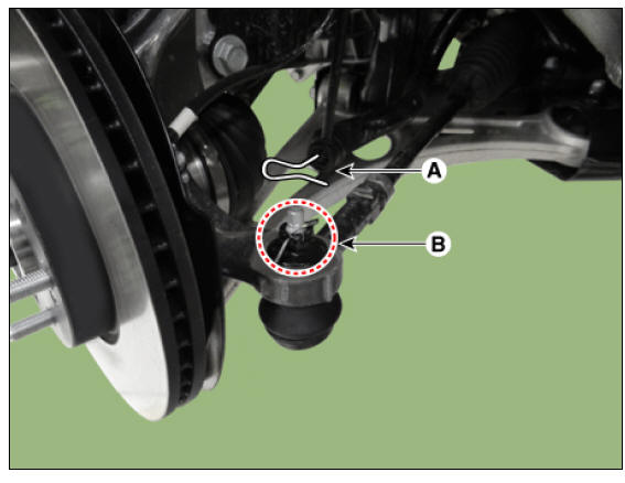
- Remove the tie rod end pin (A) and nub (B).
Tightening torque : 78.4 - 98.0 N*m (8.0 - 10.0 kgf*m, 57.8 - 72.3 lb*ft)
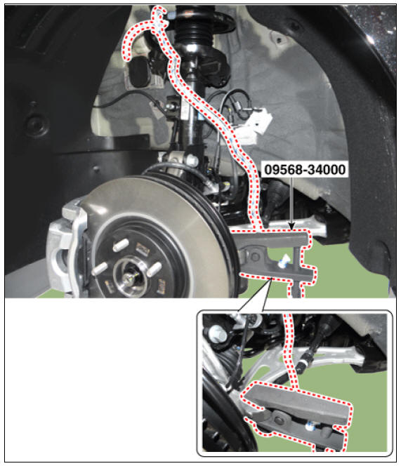
- Remove the knuckle by using the SST (09568-34000).
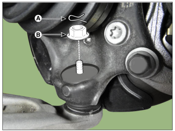
- Remove the lower arm pin (A) and nut (B).
Tightening torque : 78.4 - 98.0 N*m (8.0 - 10.0 kgf*m, 57.8 - 72.3 lb*ft)
- Remove the stabilizer link nut.
Tightening torque : 98.0 - 117.6 N*m (10.0 - 12.0 kgf*m, 72.3 - 86.7 lb*ft)
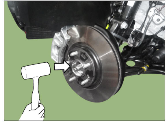
- Using a plastic hammer, disconnect driveshaft from the axle hub.
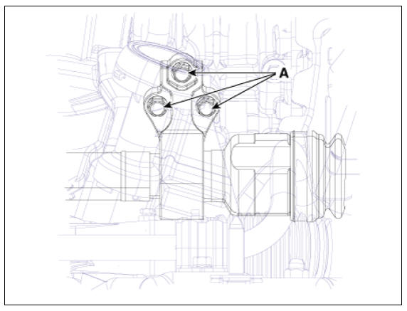
- Remove the iner shaft bearing bracket bolt (A).
Tightening torque : 49.0 - 63.7 N*m (5.0 - 6.5 kgf*m, 36.2 - 47.0 lb*ft)
- Remove the drive shaft (A).
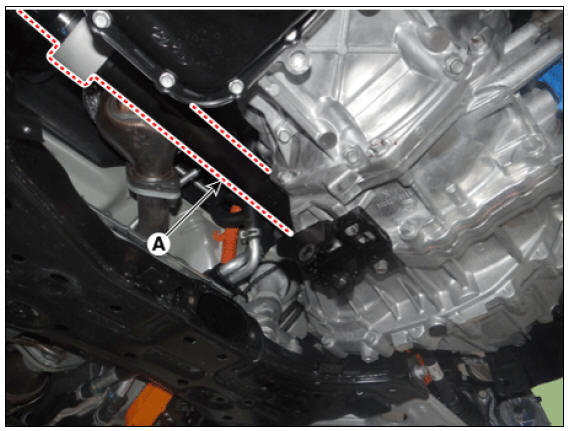
Warning
If the drive shaft could not be ejected, remove the pry bar through the space between transmission and drive shaft.
- Install in the reverse order of removal.
Warning
- Use a pry bar being careful not to damage the transaxle and joint.
- Do not insert the pry bar too deep, as this may cause damage to the oil seal.
- Do not pull the driveshaft by excessive force it may cause components inside the joint kit to dislodge resulting in a torn boot or a damaged bearing.
- Plug the hole of the transaxle case with the oil seal cap to prevent contamination.
- Support the driveshaft properly.
- Replace the retainer ring whenever the driveshaft is removed from the transaxle case.
READ NEXT:
 TJ Joint Repair procedures
Removal
Warning
Drive shaft joints require special grease, so do not add any
other type of grease.
When replacing the boot band, it must be a new one.
Remove the front drive shaft.
(Refer to Driveshaft Assembly - "Front Drive
Driveshaft Assembly
Removal
The type can replace the wheel side joint boot
Remove the front driveshaft.
(Refer to Driveshaft Assembly - "Front driveshaft")
Remove the transaxle side joint.
(Refer to Driveshaft Assembly - "Joint Assembly(Tra
Front Hub / Knuckle
Components
Brake disc
Hub assembly
Dust cover
Knuckle
Front Hub / Knuckle / Repair Procedures
Removal
Remove the wheel and tire.
Tightening torque :
107.9 - 127.5 N*m (11.0 - 13.0 kgf*m, 79.6 - 94.0 lb*ft)
Warning
Be c
SEE MORE:
Accelerator Position Sensor (APS)
Specification
Accelerator Position Sensor (APS) Description and operation
Description
Installed on the accelerator pedal module, the Accelerator Position Sensor (APS)
detects the rotation
angle of the accelerator pedal. The APS is one o
AVN System / Description And Operation
AVN System / Components And Components Location
AVN head unit
External amplifier
Crash pad LTE antenna
Roof LTE antenna
Multimedia jack
Steering wheel remote control (SWRC)
Hands-free mic (Built-in overhead console)
Description
Categories
- Home
- KIA Niro EV, Hybrid - Second generation - (SG2) (2021-2024) - Owner's manual
- Kia Niro - First generation - (DE) (2017-2022) - Service and Repair Manual
- Contact Us