KIA Niro: Hybrid Power Control Unit (HPCU)/ Repair procedures
Warning
- Be sure to read and follow the "General Safety Information and Caution" before doing any work related with the high voltage system. Failure to follow the safety instructions may result in serious electrical injuries.
- Be sure to shut off the high voltage before doing any work related with the high voltage system(Refer to "High Voltage Shutoff Procedure"). Failure to follow the safety instructions may result in serious electrical injuries.
- Shut off the high voltage circuit.
(Refer to Hybrid Control System - "High Voltage Shutoff Procedure")
- Remove the air cleaner assembly and air duct.
(Refer to Engine Mechanical System - "Air Cleaner")
- Remove the ECM & TCM bracket assembly.
(Refer to Engine Control/Fuel System - "Engine Control Module")
- Drain the coolant of hybrid motor cooling system.
(Refer to Hybrid Motor Cooling System - "Coolant")
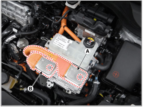
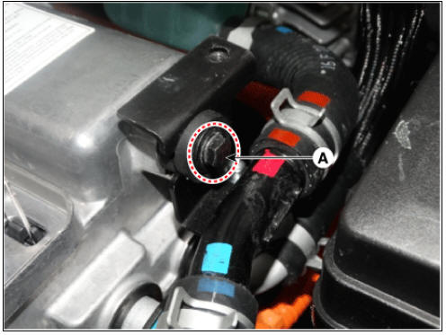
- Disconnect the motor power cable connector (A) and HSG power cable connector (B) after loosening the mounting bolts.
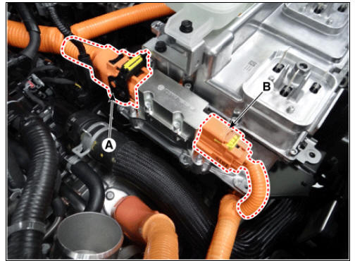
- Disconnect the power cable (A) and inverter power cable (B) from the HPCU.
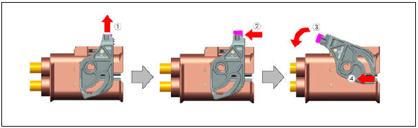
Warning
Remove the inverter power cale in the follwing order.
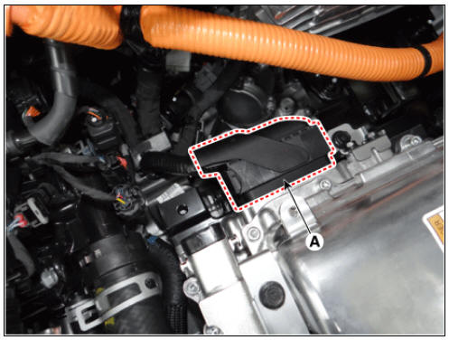
- Disconnect the HCU & inverter (MCU) connector (A).
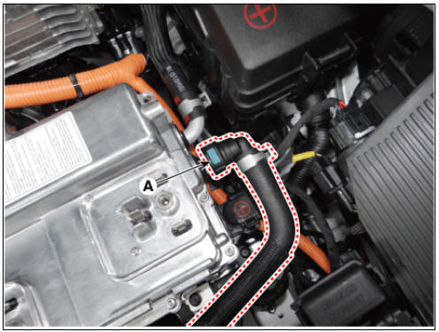
- Disconnect the coolant outlet hose & pipe after loosening the mounting bolt (A).
- Disconnect the coolant inlet hose quick-connector (A).
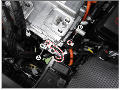
- Remove the LDC power outlet cable mounting bolt (A) and ground cable bolt (B).
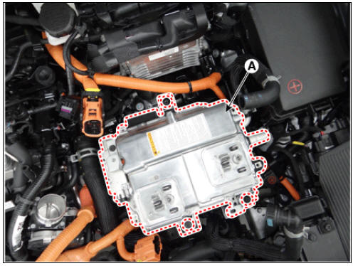
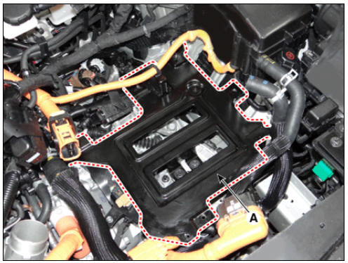
- Remove the HPCU (A) after loosening the mounting bolts.
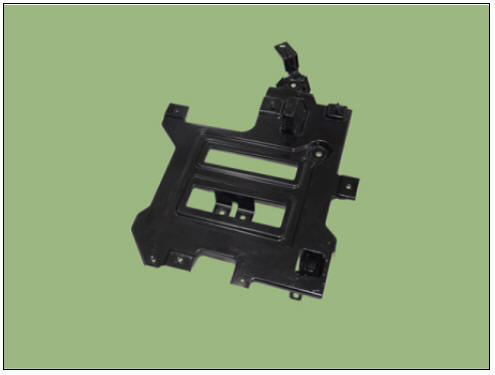
Hybrid Power Control Unit (HPCU) Tray
- Remove the hybrid power control unit.
(Refer to Hybrid Control System - "Hybrid Power Control Unit (HPCU)")
- Remove the hybrid power control unit tray (A) after loosening the mounting bolts.
Hybrid Power Control Unit (HPCU) tray mounting bolt : 21.6 - 23.5 N*m (2.2 - 2.4 kgf*m, 15.9 - 17.4 lb*ft)
Installation
Warning
Be sure to read and follow the "General Safety Information and Caution" before doing any work related with the high voltage system. Failure to follow the safety instructions may result in serious electrical injuries.
- Install the HPCU in the reverse order of removal.
- Refill the hybrid motor cooling system coolant and perform air bleeding
by using the KDS.
(Refer to Hybrid Motor Cooling System - "Coolant")
Warning
Perform HCU Variant Coding and Engine Clutch / Motor Resolver learning after replacing the HPCU.
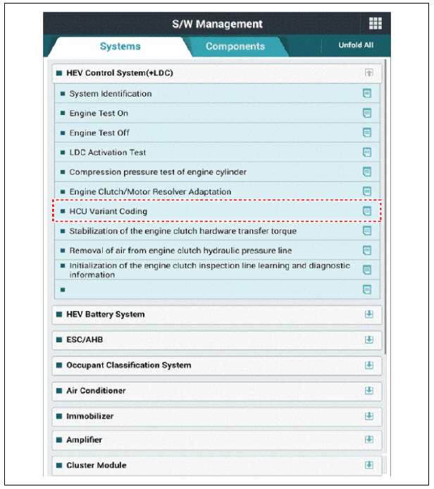
HCU Variant Coding
- Turn the ignition switch OFF.
- Connect the KDS to Data Link Connector (DLC).
Turn the ignition switch ON.
- Select "Vehicle, Model year, Engine, System".
- Select "Vehicle S/W Management".
- Select "HCU Variant Coding".
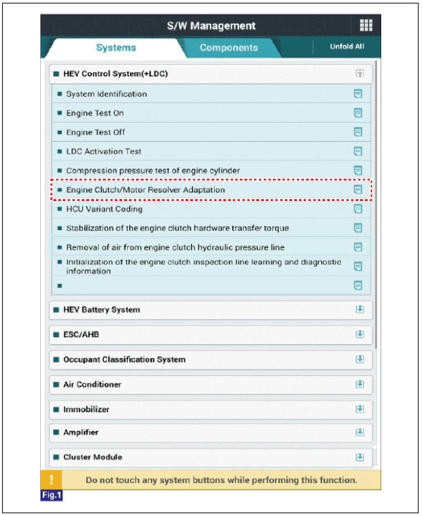
Engine clutch/motor resolver adaptation
- Turn the ignition switch OFF.
- Connect the KDS to Data Link Connector (DLC).
Turn the ignition switch ON.
- Select "Vehicle, Model year, Engine, System".
- Select "Vehicle S/W Management".
- Select "Engine clutch/motor resolver adaptation.".
HCU Terminal And Input/Output Signal

Terminal Function
Connector (C133-S)
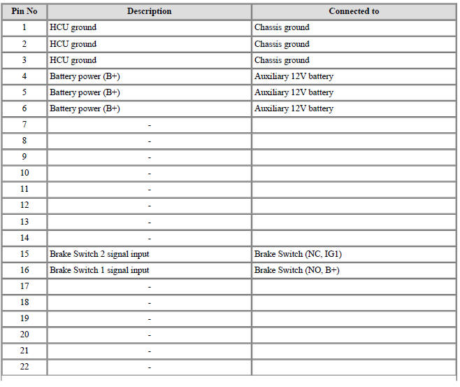
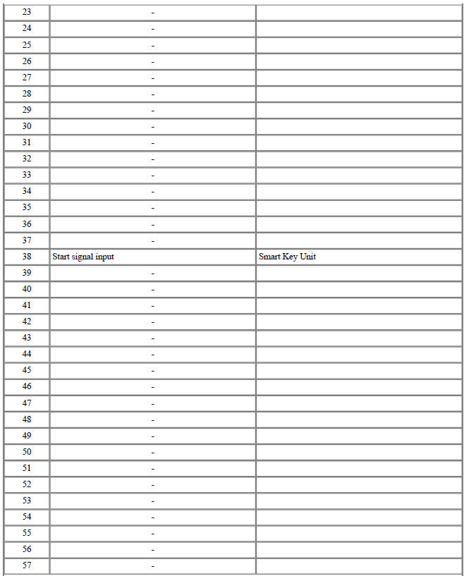
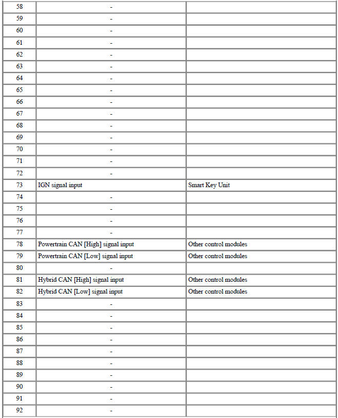

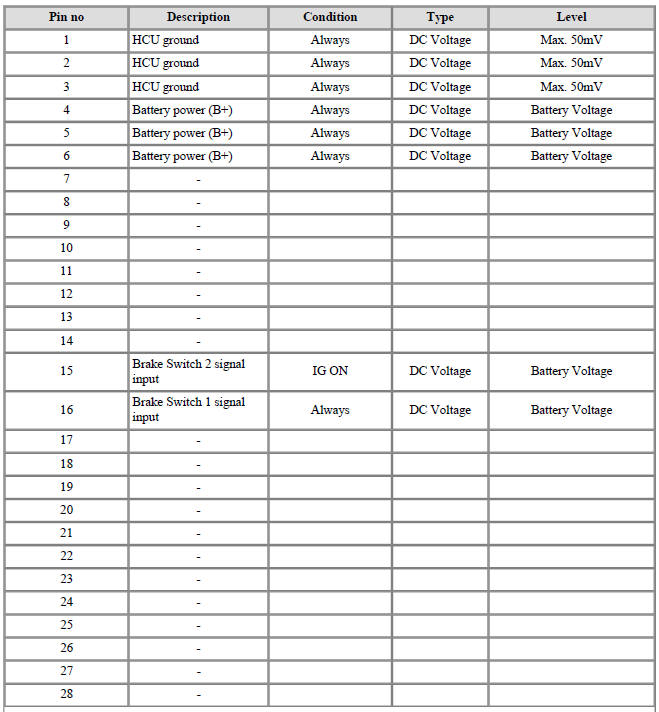
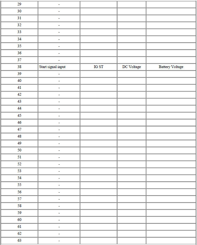
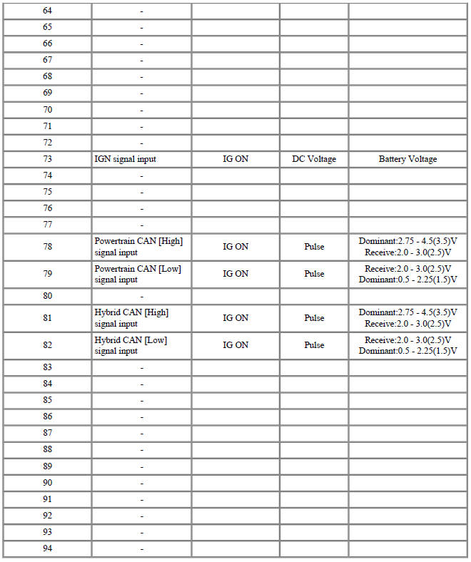
Input/Output signal
Connector (C133-S)
Circuit Diagram
Hybrid Control Unit (HCU) Repair procedures
Removal
Warning
- Be sure to read and follow the "General Safety Information and Caution" before doing any work related with the high voltage system. Failure to follow the safety instructions may result in serious electrical injuries.
- Be sure to read and follow the "High Voltage Shut-off Procedures" before doing any work related with the high voltage system. Failure to follow the safety instructions may result in serious electrical injuries.
- Refer to "HPCU".
Warning
The HCU is integrated into the HPCU that can't be disassembled. So refer to "HPCU" for the removal or installation procedure of the HCU.
Installation
Warning
- Be sure to read and follow the "General Safety Information and Caution" before doing any work related with the high voltage system. Failure to follow the safety instructions may result in serious electrical injuries.
- Be sure to read and follow the "High Voltage Shut-off Procedures" before doing any work related with the high voltage system. Failure to follow the safety instructions may result in serious electrical injuries.
- Refer to "HPCU".
Warning
The HCU is integrated into the HPCU that can't be disassembled. So refer to "HPCU" for the removal or installation procedure of the HCU.
Specification

READ NEXT:
 DC Fuse
Component Location
DC Fuse
Inverter Connector (↔ Power Relay Assembly (PRA))
Inverter Connector (↔ Electric A/C compressor)
Component Location
Harness Connector
Inverter - Removal
Warning
Be sure to read and
High Voltage Battery System / Components And Components Location / Repair Procedures
Description
The High Voltage Battery System provides the hybrid drive motor, HSG, and electric A/C compressor
with electric energy and also reserves the electric energy generated during regeneration braking.It
consists of the battery pack assemb
SEE MORE:
Transmission Gear Oil Repair procedures
Oil Level Check
Inspection
Remove the under cover.
(Refer to Engine Mechanical System - "Engine Room Under Cover")
Remove the oil filler plug (A or B).
Check the condition of the oil and make sure that it is at the proper
Rear Cross-Traffic Collision-Avoidance Assist malfunction
A: Check blind-spot safety systems
When Rear Cross-Traffic Collision-
Avoidance Assist is not working properly,
the warning message will appear on
the cluster for several seconds, and the
master ( ) warning light will
appear on
the cluste
Categories
- Home
- KIA Niro EV, Hybrid - Second generation - (SG2) (2021-2024) - Owner's manual
- Kia Niro - First generation - (DE) (2017-2022) - Service and Repair Manual
- Contact Us