KIA Niro: Positive Crankcase Ventilation (PCV) Valve Repair procedures | Canister Repair procedures
Removal
- Disconnect the vapor hose (A).
- Remove the PCV valve (B).

Inspection
- Insert a thin stick (A) into the PCV valve (B) from the threaded side to check the plunger movement.

Warning
If the plunger does not move (PCV valve is clogged), clean or replace the valve.
Installation
- Install in the reverse order of removal.
PCV valve :
1.96 - 2.94 N*m (0.2 - 0.3 kgf*m, 1.45 - 2.17 lb*ft)
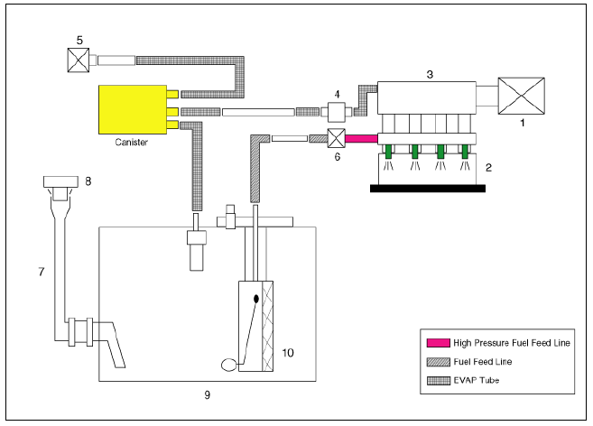
Schematic Diagram

- Air cleaner
- Delivery pipe & injector
- Engine
- Purge control solenoid valve (PCSV)
- Fuel tank air filter
- High pressure fuel pump
- Fuel filler hose
- Fuel filler cap
- Fuel tank
- Low pressure fuel pump
Canister
Canister is filled with charcoal and absorbs evaporated vapor in fuel tank. The gathered fuel vapor in canister is drawn into the intake manifold by the ECM/PCM when appropriate conditions are set.
Purge Control Solenoid Valve (PCSV)
Purge Control Solenoid Valve (PCSV) is installed in the passage connecting canister and intake manifold. It is a duty type solenoid valve and is operated by ECM/PCM signal.
To draw the absorbed vapor into the intake manifold, the ECM/PCM will open the PCSV, otherwise the passage remains closed.
Fuel Filler Cap
A ratchet tightening device on the threaded fuel filler cap reduces the chances of incorrect installation, which would seal the fuel filler. After the gasket on the fuel filler cap and the fill neck flange contact each other, the ratchet produces a loud clicking noise indicating the seal has been set.
Canister Repair procedures
Description
Evaporative Emission Control System prevents fuel vapor stored in fuel tank from vaporizing into the atmosphere. When the fuel evaporates in the fuel tank, the vapor passes through vent hoses or tubes to
the canister filled with charcoal and the canister temporarily holds the vapor in the charcoal. If ECM
determines to draw the gathered vapor into the combustion chambers during certain operating
conditions, it will use vacuum in intake manifold to move it.
Removal
- Turn ignition switch OFF and disconnect the negative (-) battery terminal.
- Remove the fuel tank.
(Refer to Engine Control / Fuel System - "Fuel Tank")
- Disconnect the vapor tube quick-connector (A).
- Remove the canister (B) from the fuel tank after loosening the bolts (C).

- Disconnect the fuel tank isolation valve (FTIV) connector (A).
- Disconnect the vapor tube quick-connector (B).
- Disconnect the vapor hose (C).

- Remove the fuel tank isolation valve (B) from the canister after loosening the bolts (A).


Inspection
- Check for the following items visually.
- Cracks or leakage of the canister
- Loose connection, distortion, or damage of the vapor hose/tube

A: Canister → Atmosphere
B: Canister → Intake Manifold
C: Canister → Fuel Tank
Installation
- Install in the reverse order of removal.
READ NEXT:
 Fuel Tank Air Filter Repair procedures
Fuel Filler Cap Description and operation
Description
A ratchet tightening device on the threaded fuel filler cap reduces the
chances of incorrect installation, which seals the fuel
filler. After the gasket on the fuel filler cap and the filler
 Exhaust Emission Control System
Description
Exhaust emissions (CO, HC, NOx) are controlled by a combination of engine
modifications and the
addition of special control components.
Modifications to the combustion chamber, intake manifold, camshaft and ignition
system form t
SEE MORE:
 Seat Heater Repair procedures
Inspection
Front Seat Heater
Check for continuity and measure the resistance between power terminal
(heater : 3, ventilation : 4) and
ground terminal (6).
Standard value
Driver / Assists (cushion + back)
Heater seat : 1.77Ω+-10%/23Ă
 Protection Of The Vehicle
Always be sure to cover fenders, seats, and floor areas before starting work.
Warning
The support rod must be inserted into the hole near the edge of the
hood whenever you inspect the
engine compartment to prevent the hood from falling and causi
Categories
- Home
- KIA Niro EV, Hybrid - Second generation - (SG2) (2021-2024) - Owner's manual
- Kia Niro - First generation - (DE) (2017-2022) - Service and Repair Manual
- Contact Us
