KIA Niro: Emission Control System
Kia Niro - First generation - (DE) (2017-2022) - Service and Repair Manual / Emission Control System
Components Location

- PCV Valve
- Canister
- Purge Control Solenoid Valve (PCSV)
- Fuel Tank Pressure Sensor (FTPS)
- Fuel Level Sensor (FLS)
- Fuel tank air Filter
- Catalytic converter (WCC)
- Gasoline Particulate Filter (GPF)
 PCV Valve
 Canister
 Purge Control Solenoid Valve (PCSV)
 Fuel Tank Pressure Sensor (FTPS)
 Fuel Level Sensor (FLS)
 Fuel tank air Filter
 Catalytic converter (WCC)
 Gasoline Particulate Filter (GPF)
Description
Emissions Control System consists of three major systems.
- The Crankcase Emission Control System prevents blow-by gas from
releasing into the atmosphere.
This system recycles gas back into the intake manifold (Closed Crankcase Ventilation Type).
- The Evaporative Emission Control System prevents evaporative gas from
releasing into the
atmosphere. This system burns gas at appropriate engine operating condition after gathering it in
the canister. - The Exhaust Emission Control System converts the three pollutants (hydrocarbons
(HC), carbon
monoxide (CO), and oxides of nitrogen (NOx)) into harmless substances by using the 3-way
catalytic converter.
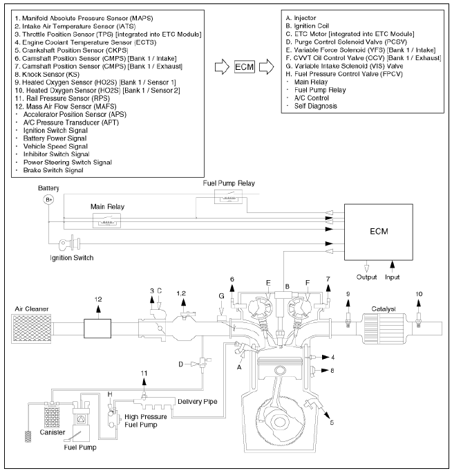
Schematic Diagram

Troubleshooting

- Crankcase Emission Control System
- Positive Crankcase Ventilation (PCV) Valve Repair procedures | Canister Repair procedures
- Fuel Tank Air Filter Repair procedures
- Exhaust Emission Control System
- The Gasoline Particulate Filter (GPF)
READ NEXT:
 Crankcase Emission Control System
Schematic Diagram
Repair procedures
Inspection
After disconnecting the vapor hose from the PCV valve, remove the PCV
valve.
Reconnect the PCV valve to the vapor hose.
Run the engine at idle, then put a finger over the open end of the
 Positive Crankcase Ventilation (PCV) Valve Repair procedures | Canister Repair procedures
Removal
Disconnect the vapor hose (A).
Remove the PCV valve (B).
Inspection
Insert a thin stick (A) into the PCV valve (B) from the threaded side to check the plunger movement.
Warning
If the plunger does not move (PCV
SEE MORE:
 Pre-Charge Relay
Specification
Description
The Power Relay Assembly (PRA) consists of the positive and negative main
relays, pre-charge relay, pre-charge resistor and
battery current sensor. It is located inside the battery pack assembly and
controls the h
 Inverter kit / Body kit
Remove the battery (-) cable.
Disconnect the high voltage circuit. (Refer to Generals)
Use the recovery/reproduction/charging device to recover the coolant.
Warning
When removing the connector between the vehicle and the
compressor,
Categories
- Home
- KIA Niro EV, Hybrid - Second generation - (SG2) (2021-2024) - Owner's manual
- Kia Niro - First generation - (DE) (2017-2022) - Service and Repair Manual
- Contact Us
