KIA Niro: Power Door Lock Switch Repair procedures
Kia Niro - First generation - (DE) (2017-2022) - Service and Repair Manual / Body Electrical System / Power Door Locks / Power Door Lock Switch Repair procedures
Inspection
Non-IMS Type
- Check for continuity between the terminals. If there is an abnormality, replace the switch.
IMS Type
Diagnosis With KDS
- The body electrical system can be quickly diagnosed for failed parts by
using vehicle diagnostic
system (KDS).
The diagnostic system (KDS) provides the following information.
(1) Self diagnosis : Checks and displays the failure code (DTC)
(2) Current data : Checks the system input/output data state
(3) Actuation test : Checks the system operating condition
(4) Additional function : Other controls such as the system option and zero point
- Select the 'Car model' and the system to be checked in order to check the vehicle with the tester.
- Select the 'Body Control Module (BCM)' to check the driver seat or assist door module (DDM/ ADM).
- Select the "Current Data" menu to check the current state of the
input/output data.
The input/output data for the sensors corresponding to the driver seat or assist door module (DDM/ ADM) can be checked.
- To check the power door lock operation by force, select "Actuation test".
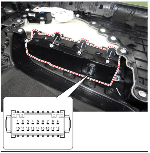
Removal
- Remove the power window main switch.
(Refer to Power Window - "Power Window Switch")
Installation
- Install in the reverse order of removal.
READ NEXT:
 Power Door Mirrors
Power Door Mirrors / Components And Components Location
Power door mirror
Power door mirror switch
Power folding mirror switch
Connector and Terminal Function
Driver Power Window Switch (Non-IMS Type)
Driver Power Window Swit
Power Door Mirror Switch Repair procedures
Inspection
Non-IMS Type
Disconnect the negative (-) battery terminal.
Remove the front left door trim.
(Refer to Body - "Front Door Trim")
Disconnect the power mirror switch connector from the door trim.
Check for conti
Power Door Mirror Actuator
Power Door Mirror Actuator Components and components location
Power Door Mirror Actuator Repair procedures
Inspection
Disconnect the negative (-) battery terminal.
Remove the front door quadrant inner cover (A).
Disconnect the p
SEE MORE:
Rear door locks
Child-protector rear door lock (if equipped)
Operation
Insert the mechanical key.
Turn the child safety lock to the lock
position (1).
To allow a rear door to be opened
from inside the vehicle, unlock the
child safety lock.
To op
Front Radar Unit
Specification
Circuit Diagram
Front Radar Unit Repair Procedures
Inspection
Warning
Put the vehicle on the level ground.
Take out heavy luggage from the vehicles' seats or tailgate.
Set all tires according to the specified pressur
Categories
- Home
- KIA Niro EV, Hybrid - Second generation - (SG2) (2021-2024) - Owner's manual
- Kia Niro - First generation - (DE) (2017-2022) - Service and Repair Manual
- Contact Us